
This is the construction and application thread for the Stereo Insert Switcher.
Mastering Stereo Insert Switcher PC Board: https://ka-electronics.com/shop/index.p ... rch=insert
Features
Full bypass with fully-balanced hot/cold switching. Fully passive.
Two Inserts with Flip.
Backbone signal flows through the connections on the left to the right.
Insert connections are on a 25 pin D in a modified Tascam format.
AES Tascam-format DB-25 breakout cables from Hosa (AES-803T), Mogami (GOLD AES TD DB25 XLR-03), Planet Waves and others may be used. (To use AES cables with the Insert Switcher the male and female XLR breakout connectors need to be reversed.)
Normal signal flow is Left/Right In > Insert 1 > Insert 2 > Left/Right Out.
Flipped signal flow is Left/Right In > Insert 2 > Insert 1 > Left/Right Out.
Cascadable using additional boards in series for more backbone inserts.
Configurable as an three Input Selector using the backbone and return inputs.
Sealed low signal current relays.
Socketed relays are user-replaceable.
No logic required: Uses sustained/latching SPST push button or toggle switches.
LED outputs. (Current-limited to 10 mA; 24V/2K21Ω.)
Isolated audio, relay and chassis grounds.
Series-parallel coil connections reduce power consumption and heat.
Relay coils are 12V, control supply is 24V.
Can be powered from low-cost 24V switching supplies.
Mechanical and Power Specifications
Board Size: 3.8" x 2.75"
Mounting holes: M3 0.125" diameter on a 3.5" x 2.45" pattern.
Assembled Board Size: Height: 0.7"; Depth with DB-25 Connector 4.0" overall, 3.8" depth behind panel.
Power Requirements: Coil current using Omron G5V-2-H1-DC12 relays, 14 relays and 3 LEDs on, 120 mA typical 2.82 W. Low sensitivity relays are not recommended as they consume 7.7 W under similar conditions.
Bill of Materials
Update 4/27/23. Added Phoenix connectors and relay sockets to the Mouser Project Manager BOM: https://www.mouser.com/ProjectManager/P ... e32774ab41
The insert switcher can be built as a two insert switcher with flip, an insert switcher without flip a single insert/bypass or two independent insert/bypass..
The bill-of-materials is for a two insert with flip.
The Mouser BOM cannot be edited.
To edit, load it into the shopping cart.
Remove the number of relays as needed.
A fully-configured switcher uses 14 relays.
Without flip 8 relays are required.
A single insert uses only 4 relays.
For XLR I/O or hardwired applications do not install the 25 pin D connector and wire directly to the board.
A Mouser bill-of-materials with 14 Omron relays is here: https://www.mouser.com/ProjectManager/P ... 446ab230fc
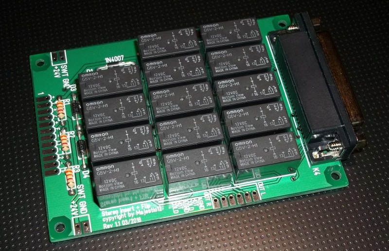
Stereo Mastering Insert Switcher PC Board, Fully Balanced, Passive, Two Insert with Flip.
Schematic

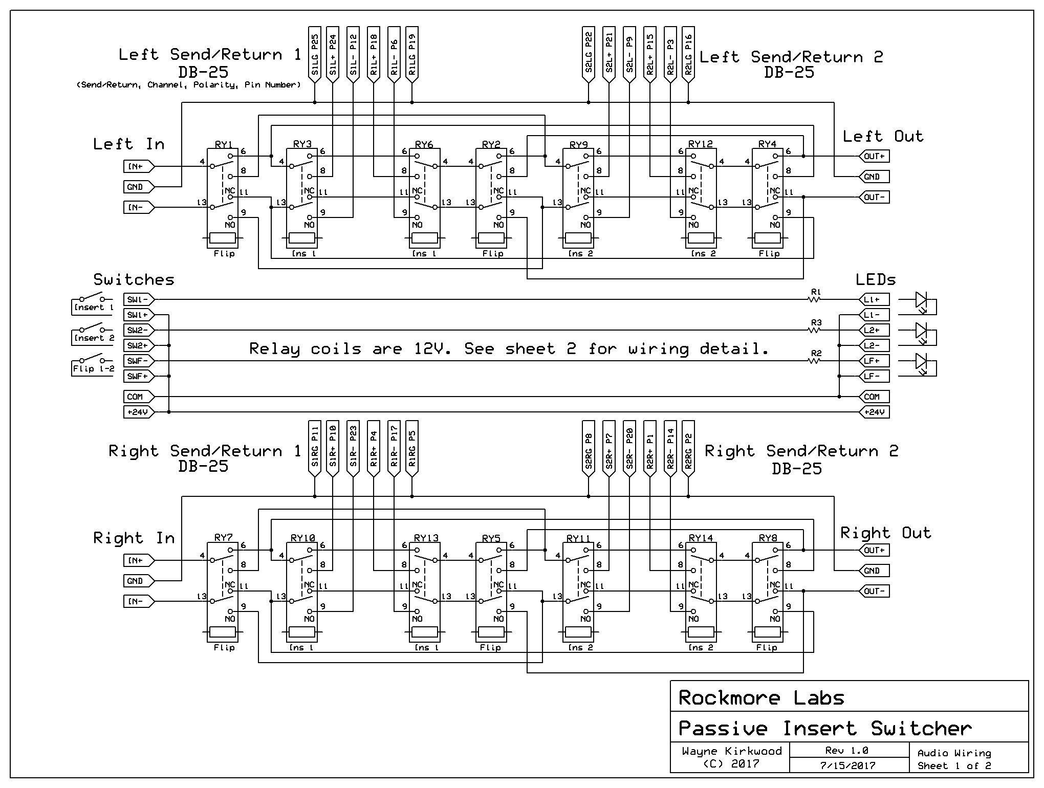
Mastering Insert Switcher Schematic, Audio Flow, Sheet 1
Larger Image: https://www.proaudiodesignforum.com/ima ... heet_1.png
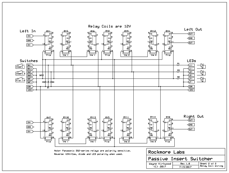
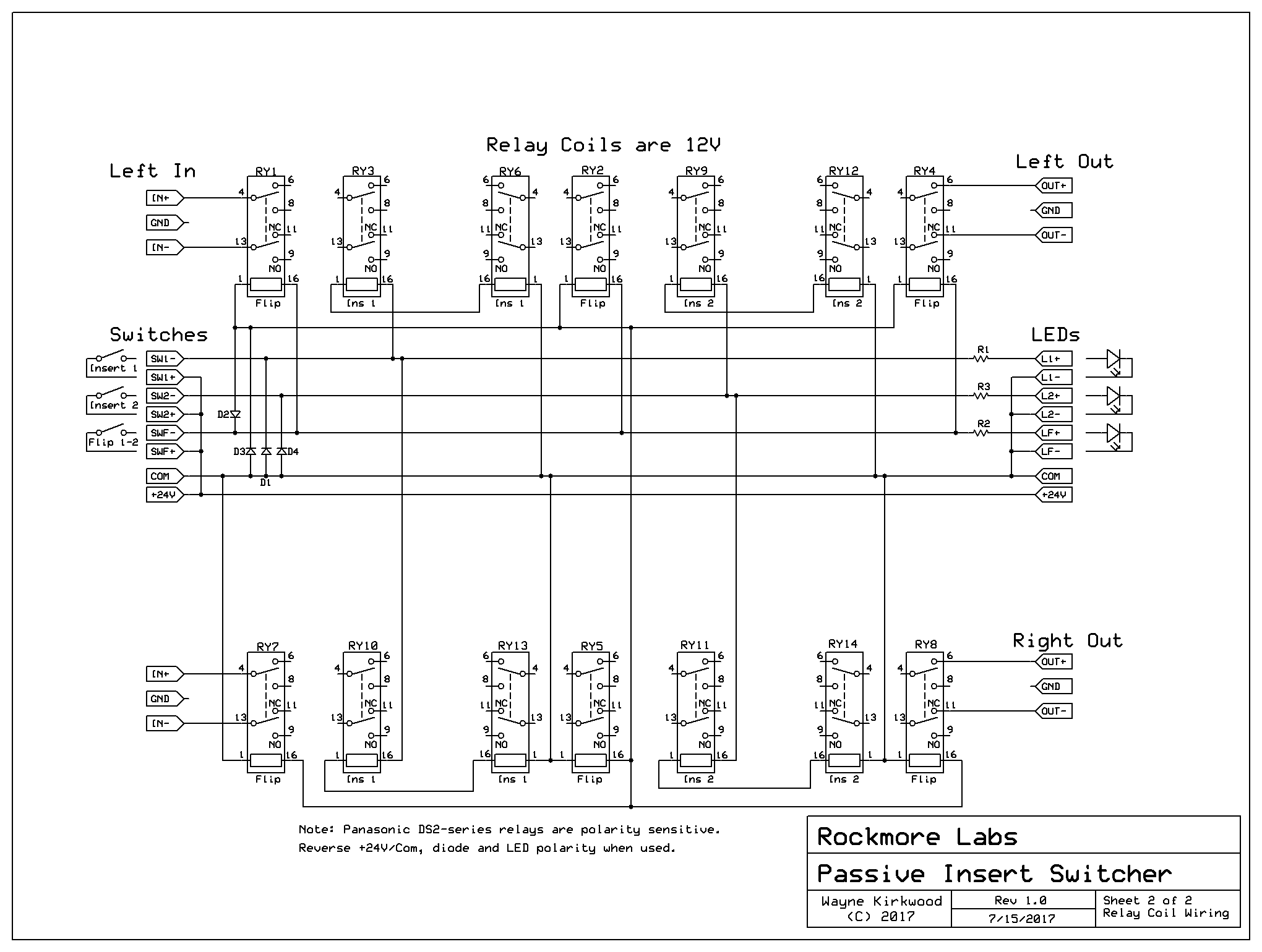
Mastering Insert Switcher Schematic, Relay Coil Wiring, Sheet 2
Larger Image: https://www.proaudiodesignforum.com/ima ... heet_2.png
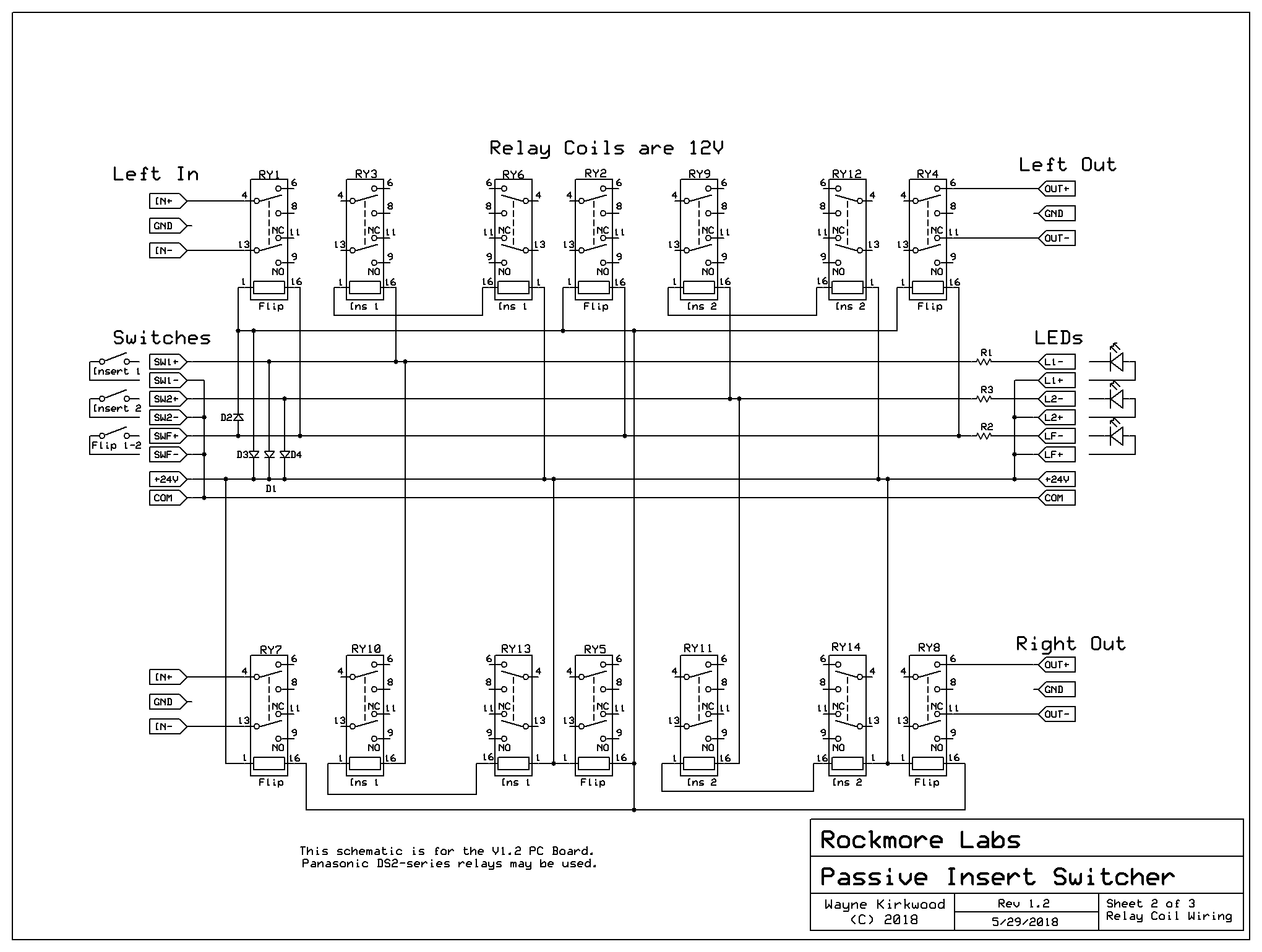
V1.2 Board
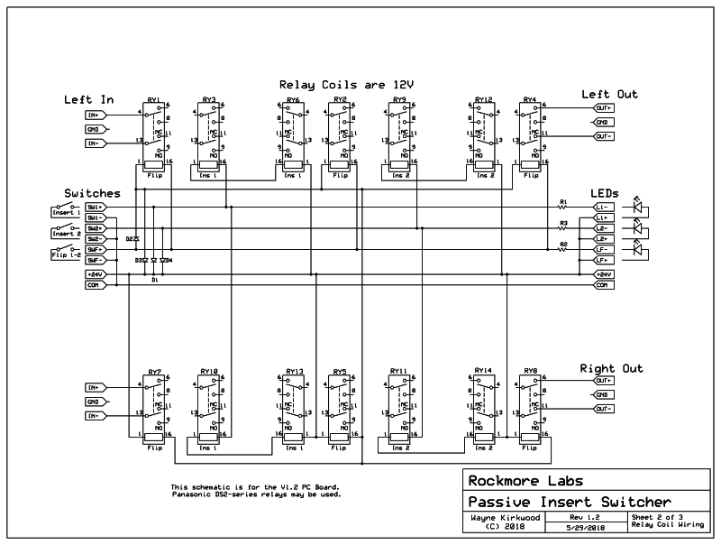
Mastering Insert Switcher Schematic, Relay Coil Wiring, Sheet 3
Larger Image: https://www.proaudiodesignforum.com/ima ... heet_3.png
A note about relays
The relay coil requirements are 12V.
The control supply is 24V: A series/parallel connection is used to reduce current.
The Mouser BOM specifies Omron G5V-2-H1-DC12 "H1" high-sensitivity relays.
With all relays engaged the 24V supply current is about 135 mA.
Panasonic DS2Y relays are polarity sensitive.
On boards before V1.2:
Do not use Panasonic relays unless you intend to reverse the control supply, diode and LED polarity.
Omron, Fujitsu, Takamisawa etc. do not have a coil polarity requirement.
On V1.2 boards Panasonic DS2Y relays may be used.
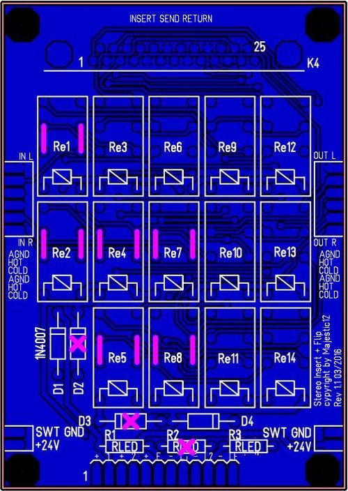
Two Inserts with Flip
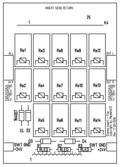
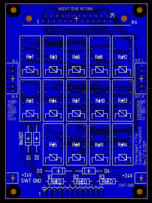
Stereo Mastering Insert Switcher PC Board Stuffing Diagram.
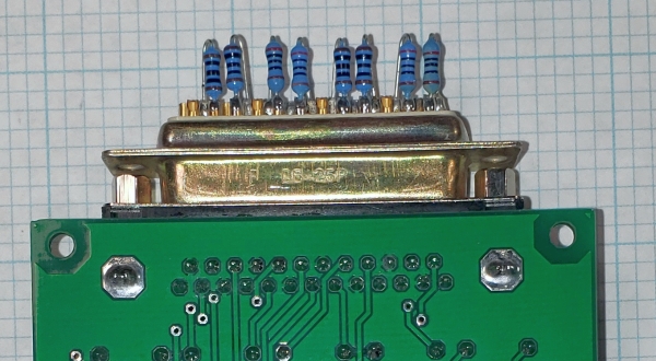
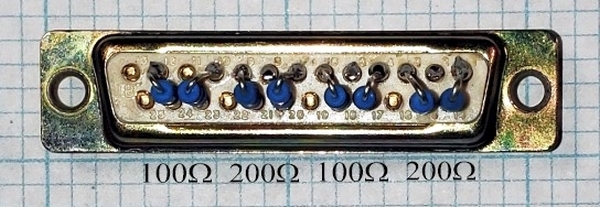
DB-25 Insert Connector Pinout
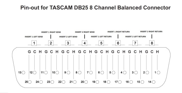
Stereo Mastering Insert Switcher PC Board, Tascam DB-25F Breakout Cable Pinout
You can get breakout cables here:
The insert switcher uses a female DB-25.
Planet Waves provides breakout cables which are also DB-25F.
To use the breakout cables male-to-male snakes are available in various lengths from 5-25 feet.
Female DB25F to Stripped Ends: http://www.amazon.com/Planet-Waves-PW-C ... B001PGXIUM
Male DB25M to DB25M 5' Snake: http://www.amazon.com/Planet-Waves-Modu ... B001G7J2EG
Relay and LED Connections
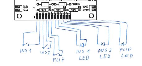
Stereo Mastering Insert Switcher PC Board, Relay Control and LED Connector Pinout
Other Configurations
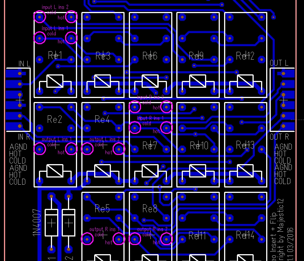
To eliminate the Flip function do not install six relays.
The normally-closed contacts of the flip relays are jumpered (shown in pink).
The relays that are used are RE3, 6, 9, 10, 11, 12, 13 and 14.
The relays that are not used are RE1, 2, 4, 5, 7, 8.
Two Inserts without Flip
Stereo Mastering Insert Switcher PC Board Stuffing Diagram without Flip.
Single Insert or Full Bypass
The normally-closed contacts of the Insert 2 and flip relays are jumpered.
Install relays at RE3, 6, 10, 13.
The relays that are not used are RE1, 2, 4, 5, 7, 8, 9, 11, 12, 14.
Split Backbone. Two Independent Full Bypass.
I/O points are at the flip relays.
Stereo Mastering Insert Switcher PC Board Stuffing Diagram for Split Backbone. Useful for Two Independent Full bypass.
Larger version: https://www.ka-electronics.com/images/j ... _Large.jpg