A Flat Moving Coil Preamp Using Paralleled Amplifiers

Where we discuss new analog design ideas for Pro Audio and modern spins on vintage ones.
User avatar
JR.
Posts: 3704
Joined: Sat May 24, 2008 7:21 pm
Contact:

Re: A Flat Moving Coil Preamp Using Paralleled Amplifiers

Post by JR. »

mediatechnology wrote:Thanks Richard.

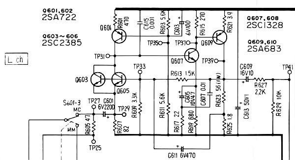
One thing that's not obvious in that circuit is the collector load.
For our readers it's the grounded 1K at the output.
I also spotted a non-floating supply version having separate collector loads to split supplies.

The common base topology looks ideal.

I tried a THAT1512 in common base with In+ and In- grounded.
It's similar topology to the mic preamp-based summing amp circuits you see in the SSM applications.

Balanced input is fed to Rg+ and Rg-.
The cartridge and termination, in parallel, serve as Rg and set gain.

It works, but the internal resistor values of the 1512 are not suitable and it doesn't lend itself to paralleled devices.
There are also active current sinks in the NPN emitters vs. resistors to improve linearity in mic preamp applications.
A single 1512 in this configuration isn't quiet enough.
There's also no control of gain - it's determined by the cartridge and it's termination.

There just aren't many common-base audio circuits for moving coil preamps published.
I've been asking myself "Why aren't there any common-base opamp-assisted fully-differential instrumentation input high gain moving coil preamps?"

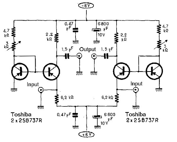
I found this gem which was apparently published by Jean Hiraga in "L'Audiophile."

Image
Common Base Moving Coil Phono Preamp, Jean Hiraga, L'Audiophile.

It's not as simple or elegant as Leach and Lee but it is floating input.
It looks very similar in a way to Leach's "Current Mirror" common base moving coil preamp only with all PNP and has split balanced inputs.
I don't think the original Hiraga used 2SB737s.

Seems like Hiraga could be used with helper op amps to have more gain than a head amp.

What's cool about the Hiraga is that it is a common base differential pair....
You just don't see those often.
I don't think that is a differential. The extra transistors are just ground connected using a variable DC current to they can bias the input device emitter to be 0V so it can be DC coupled. The extra junction's noise is adding to the input device so not the quietest solution. A few thousand uF shunt across those devices wouldn't hurt.

I am not aware that toshiba ever made 2sb737s.. they were developed by a small Japanese company (Toyo something) for head amps. First ROHM distributed the parts then bought the company and branded them ROHM.

FWIW I've never been a huge fan of common base preamps. What is the input impedance of an emitter? Pretty damn low and not very linear(?).

JR
Cancel the "cancel culture", do not support mob hatred.
User avatar
mediatechnology
Posts: 5452
Joined: Sat Aug 11, 2007 2:34 pm
Location: Oak Cliff, Texas
Contact:

Re: A Flat Moving Coil Preamp Using Paralleled Amplifiers

Post by mediatechnology »

I don't think that is a differential. The extra transistors are just ground connected using a variable DC current to they can bias the input device emitter to be 0V so it can be DC coupled. The extra junction's noise is adding to the input device so not the quietest solution. A few thousand uF shunt across those devices wouldn't hurt.
I think the cartridge is designed to connect between the two inputs with balanced output taken from the collectors.
But it could just be left and right except that the build I recall seeing appeared balanced because it had two of these circuits and talked of balancing the halves to reduce cartridge current.
My intention was to use both halves in a differential pair.

Yes, one transistor in each half is Vbe bias and it should be bypassed.

EDIT:
If the Vbe reference were shared between halves, noise would be in common mode.
To improve matching and reduce cartridge current, a quad array could be used to parallel input devices into two pairs sharing a common Vbe reference.
The reference's Vbe error would be in common mode and not across the cartridge.
FWIW I've never been a huge fan of common base preamps. What is the input impedance of an emitter? Pretty damn low and not very linear(?).
Well it is low but for a 5-30 Ohm source does it matter?
As I say in the following post that's why they aren't often used. (viewtopic.php?f=6&t=749&start=19)
A moving coil input, ribbon mic input or virtual ground summing node is about the only place common base makes sense.

And yes it's also non-linear. But at 100 uV to 1 mV (or virtual ground) does that matter?
User avatar
JR.
Posts: 3704
Joined: Sat May 24, 2008 7:21 pm
Contact:

Re: A Flat Moving Coil Preamp Using Paralleled Amplifiers

Post by JR. »

+1 for a virtual earth input, but the source impedance of some MC carts is even higher than the Rbb of those devices.

The Vbe changes with input current and Vbe vs current is extremely non-linear. The trans-amp VE summer had overall NF so the emitter current was held constant, and not a source of distortion.

Interesting but I remain unenthusiastic... (that said my lack of enthusiasm for vinyl is grating to some, so my apologies.)

JR

(edit) not to belabor this but if the Hiraga was mono differential, they could just ground the two bases (for less noise and less complexity) and trim the input DC error by varying the current of either emitter R.

I have pondered linearizing a common base pre by returning a feedback R to the emitter. This would keep the Vbe constant, but now the cartridge is operating purely as a current output. This would probably make the results even more cartridge dependent. never mind... (/edit)
Last edited by JR. on Sat Aug 15, 2015 11:05 am, edited 1 time in total.
Cancel the "cancel culture", do not support mob hatred.
User avatar
mediatechnology
Posts: 5452
Joined: Sat Aug 11, 2007 2:34 pm
Location: Oak Cliff, Texas
Contact:

Re: A Flat Moving Coil Preamp Using Paralleled Amplifiers

Post by mediatechnology »

JR You may have missed that Technics SL-10 schematic back at post 19.
viewtopic.php?f=6&t=749&start=19

They linearize the common base stage with voltage FB to the base.
IMHO it's pretty clever.
Gold
Posts: 683
Joined: Sat Dec 01, 2007 5:20 pm

Re: A Flat Moving Coil Preamp Using Paralleled Amplifiers

Post by Gold »

ricardo wrote: I don't think you need to worry about DL103 tracking at 2gm with its 0.5mil conical stylus.

Though the indentation eqn isn't exactly proportional to pressure this is 'equivalent' to (0.2/0.5)^2 x 2gm = 0.32gm with a 0.7x0.2 elliptical

Besides there have been several studies which show its tip mass which is the real killer ... even with soft lacquers.
Thanks. I didn't know that. I feel better now.

Wayne, Ricardo said the difficult interface is the low R Ortofon by which he must mean an SPU. I'm happy to send you my SPU if you want it.
User avatar
mediatechnology
Posts: 5452
Joined: Sat Aug 11, 2007 2:34 pm
Location: Oak Cliff, Texas
Contact:

Re: A Flat Moving Coil Preamp Using Paralleled Amplifiers

Post by mediatechnology »

Thanks Paul. I may take you up on that once I find a good preamp topology.
It's an expensive cart and I want to know I've got it right.

What I would like to wind up with is a balanced input/balanced out flat high gain MC preamp that would be interchangeable with the MM one.

My goal would be to direct-couple to the cartridge and avoid a 1000-2000 uF input coupling cap.
Even with a coupling cap there could still be significant leakage.
The DC leakage might be low in the uA range but it seems that the AC noise component could be significant to nV-level signals.
I almost never see these big caps paralleled with a film either which seems odd.

The Leach and ricardo's head amps have a floating battery supply with only the input cart lead, output load and RCA jack connecting to ground.
They're DC-coupled to the input and as Leach points out it's impossible for cartridge current to flow.

The Hiraga is DC-coupled to the cart enabled by trimming.

There's got to be a way to combine the DC-coupled approach of Hiraga (e.g. 0V at the emitter) with the common base voltage feedback circuit of the Technics using helper op amps for gain.
I'll trade a few dB of noise for an INA to get the advantages of balanced input.
User avatar
mediatechnology
Posts: 5452
Joined: Sat Aug 11, 2007 2:34 pm
Location: Oak Cliff, Texas
Contact:

Re: A Flat Moving Coil Preamp Using Paralleled Amplifiers

Post by mediatechnology »

not to belabor this but if the Hiraga was mono differential, they could just ground the two bases (for less noise and less complexity) and trim the input DC error by varying the current of either emitter R
I had thought about that too.
My thinking was that if one leg faulted to ground there could be a potential for cart burn-out.
A 10R DC cart would have a high fault current several mA.

Whether the original Hiraga intention was differential or not, it could sure be used that way.
I looked at it and saw a butterfly like the ADI-524 "Demrow" schematic.

Image
ADI-524 "Demrow/Cohen" topology.

Image
Common Base Moving Coil Phono Preamp, Jean Hiraga, L'Audiophile.

The ADI-524 not literally identical but it has the same symmetry about the vertical axis as did Hiraga.
Re-arranging the pieces of the puzzle above could easily make this a common base stage with voltage feedback to the base.

Image
Technics SL-10 Moving Coil Preamp, common base topology with AC and DC voltage feedback to the input transistor base.

The SL-10 internal MC preamp wasn't differential but the circuit fragment surrounding Q603, Q605 and Q607 could be useful particular the goings-on at TP33.
There's AC and DC feedback to the base of the common base stage.
The whole gizmo could be useful.

EDIT: Another thing that occurred to me about the nonlinearity of the common base input is that distortion is predominately even-order.

A single-ended input common base MC input might have a groovy triode distortion mechanism.
The input of an MC head amp seeing rising HF response due to lack of RIAA combined with the even-order distortion of the common base my introduce some pleasing HF color.
Could explain the obscurity or popularity of Hiraga. (not sure which.)

The fully-balanced even order distortion of the common base input would cancel once common mode rejection was realized.

I recall seeing a similar even-order non-linearity in the 1570 mic preamp output near the clipping point when looking at only one output.
The even order was clearly visible on the 'scope.
With common mode rejection realized and the even-order products distortion cancelled, the THD under the same conditions is in the triple zeros.

Are one of Leach's and ricardo's tricks the result of non-linearities in the NPN/PNP compliment cancelling each other?
I don't quite have my head wrapped around that circuit due to the floating supply.
User avatar
JR.
Posts: 3704
Joined: Sat May 24, 2008 7:21 pm
Contact:

Re: A Flat Moving Coil Preamp Using Paralleled Amplifiers

Post by JR. »

mediatechnology wrote:JR You may have missed that Technics SL-10 schematic back at post 19.
viewtopic.php?f=6&t=749&start=19

They linearize the common base stage with voltage FB to the base.
IMHO it's pretty clever.
I saw it but didn't bother to suss it out... Since you mention I reviewed and yes they bring NF to the base which in effect bootstraps or raises the input impedance (I think?). Looks like a few ten ohms of resistive termination + whatever the emitter looks like, but that input circuit dare I say it out loud looks like a "base-follower". :lol:

JR
Cancel the "cancel culture", do not support mob hatred.
User avatar
mediatechnology
Posts: 5452
Joined: Sat Aug 11, 2007 2:34 pm
Location: Oak Cliff, Texas
Contact:

Re: A Flat Moving Coil Preamp Using Paralleled Amplifiers

Post by mediatechnology »

I changed drawing to a better one so the even Q's became odd Q's.

It may raise the input impedance but it also looks like it closes the loop and sets the overall closed loop gain to +30 dB.
ricardo
Posts: 262
Joined: Sun Apr 10, 2011 7:24 am

Re: A Flat Moving Coil Preamp Using Paralleled Amplifiers

Post by ricardo »

mediatechnology wrote:Image
Common Base Moving Coil Phono Preamp, Jean Hiraga, L'Audiophile.
JR. wrote:I don't think that is a differential. The extra transistors are just ground connected using a variable DC current to they can bias the input device emitter to be 0V so it can be DC coupled. The extra junction's noise is adding to the input device so not the quietest solution. A few thousand uF shunt across those devices wouldn't hurt.
Agreed
FWIW I've never been a huge fan of common base preamps. What is the input impedance of an emitter? Pretty damn low and not very linear(?).
Non-linear might apply to single ended Common Base but certainly not to my little push-pull floating thing.
Are one of Leach's and ricardo's tricks the result of non-linearities in the NPN/PNP compliment cancelling each other?
The circuit has many subtleties that Leach hasn't cottoned on to. The reason why I've persisted with Common Base is that the distortion behaviour is perhaps the best of any simple topology. In particular it drops like a stone with level. There's indeed a huge amount of THD cancelling .. much more than with a LTP. I've got some 1980's measurements in my junk somewhere which show this.

One reason for the dearth of Common Base is that the best it can do for noise is 3dB NF. It does this when the input R is equal to Rs. This is also very close to the least distortion point. The RF guys are aware of this 'best noise & best THD @ best load matching' condition and I believe there used to be some supa dupa FM tuners which used this to obtain both supa noise & RF Intermod.

I've tried a couple of circuits where I've stuck this front end onto a OPA to use Common Emitter but none of them were actually 'better' for real life noise. That's cos Rnv was always limited by Rbb to about 3mA max Ic. These were all virtual earths cos you didn't have EVIL resistors in the way.

One of the people who persuaded me to re-surrect my circuit also built the Hiraga and reports it is not in the same ball-park for noise and/or THD. The diagram shows a stereo unit so its not balanced or differential anything.
____________________

The resistive nature of MC cartridges means they are much less fussy with loading .. unlike MMs. The only time I've seen loading do more than shift levels a bit was Dynavector who recommended 20nF (??!) to try & tame HF on one of their high output cartridges. You'd need MUCH more to make a difference with the <10R Ortofons.

That's why I'm perfectly happy to run MCs into virtual earths. :o
____________________

Wayne, if Paul is lending you a SPU, you should try one of my little circuits ... perhaps with a couple of AA Alkalines in the traditional Altoids tin :D

If you do, I'm betting you'll still be using it in 10 yrs. :mrgreen:

JR provides the missing link in the form of the Unobtainium pnp 2sb737. The npn 2sd786, Toshiba 2sc3329, Hitachi 2sc2545/6/7 are still available from International http://www.futurlec.com stores

(Edit by wk: Corrected URL of Futurlec.)

I'm thinking you could use the floating PSU to provide floating output though the input would have to be 'grounded' to one side of your output.
_____________________

If I was doing more serious work on this, I would want to provide the 'floating' PSU without introducing noise into the 0.28nV input.

Paul Kemble has a link to http://www.lcaudio.com/index.php?page=8 which is essentially my circuit powered by some photocells

Anyone have experience with these photocells? There doesn't seem to be much data on them at all :(
Post Reply