mediatechnology wrote:While looking at your P10 - and for that matter most of your designs JR - I always notice something a little different and not immediately obvious.
Thanks i generally give these designs a lot of thought.
Take the RIAA EQ network.
I've never seen another example like it though there may be some.
AFAIK I was the first and probably only one. I never did like the conventional one stage NI preamp topology.
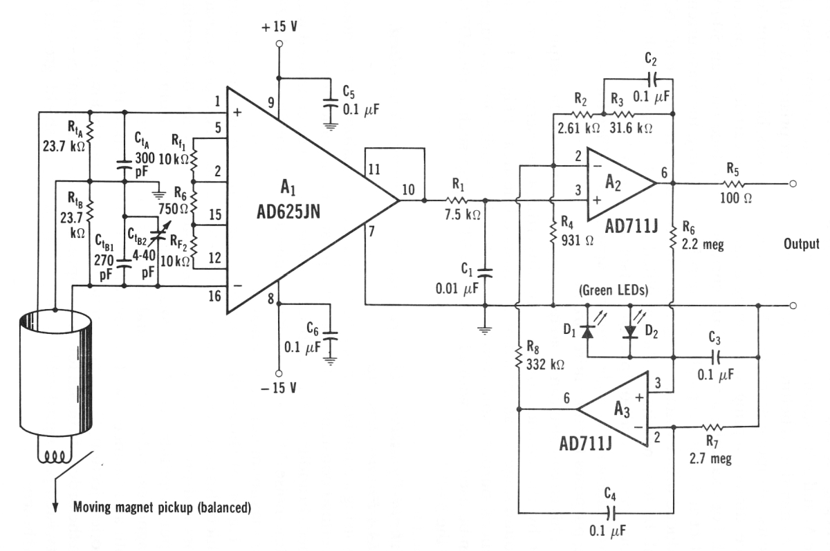
 Roberts P10 Phono Preamp RIAA Network
Most of the inverting and non-inverting "all-in-one" RIAA EQ networks typically have the feedback taken from the junction of R15 and R16.
Lets' see if I got this right:
Roberts P10 Phono Preamp RIAA Network
Most of the inverting and non-inverting "all-in-one" RIAA EQ networks typically have the feedback taken from the junction of R15 and R16.
Lets' see if I got this right:
The P10 RIAA EQ network is different: Only the 3180 us breakpoint is within the output to inverting input feedback loop.
The 3180 us breakpoint appears to be formed by R17(C7||C9) = 3178.9 us
The 318 us breakpoint is in the input leg formed by R16(C6||C8) = 317.89 us
The 75 us isn't so obvious: It's formed by (R15||R16)(C6||C8) = 9.02K * 8300 pF = 74.87 us
Yes the 3180 is the feedback pole.
The 75uSec pole and 318uSec zero is in the input network.
I don't know what your motivation actually was so let me take a guess:
By moving the feedback point to the right one node (the junction of R16.R17 vs R15.R16) the interaction between the 3180 and 318 us breakpoints is eliminated.
yes the 3180 pole is simpler, but 75 and 318 still interact.
With the conventional location used for feedback, the 75 us and 3180 interact with each other to reduce the accuracy of the 318 us point.
With the modified location, the 75 us and 318 interact, the only major consequence of which is that R15's value get's "fudged" (raised) due to R16 lowering it's Thevenin equivalent.
This approach also requires only a single precision capacitance value. (The 100 pF tolerance doesn't have to be that tight.)
Yes this was indeed part of it.. I had a couple common values of good sound quality polystyrene (I used 1000pF and 8200pF in my earlier parametric EQ)
It also appears that the network to the left of the feedback point - the 75 us and 318 us - are actually preemphasis which "bump out" the falling 3180 us response to form the proper 318 us to 75 us shelf and eventual 75 us roll off.
ding ding ding... and exactly the same result as any well executed approach that tracks RIAA accurately.
One not so subtle characteristic is that the 75uSec pole continues to roll off forever so no zero at HF like with NI topology.
A subtle consideration is that the pole in the RIAA at 3180 uSec is not hugely different than the pole in the TL07x open loop transfer function so for much of the audio range the loop gain margin (difference between open loop and closed loop gain) is in phase and constant. Sorry this was pretty tweaky and well over the head of most customers. In theory making the input error voltage more well behaved should help, while arguably over-engineered.
Today in hindsight I might claim that I used the inverting topology to eliminate the FET input distortion from mismatched impedance.

(but that would be a lie)
For the rest of the story, No less than Stanley Lipshitz (of Waterloo University fame) pointed out an error in my 75uSec math due to reactance of the series coupling caps. The error was only 1 or 2% IIRC but to make it closer to perfect (on paper at least) I replaced the .33uF cap with a 20 ohm resistor. The .15uF cap (optional IEC 7950 uSec pole) got an added 510 ohm resistor in series to tweak the 75/318 uSec time constants to be precisely on RIAA centers.
I have some nice 8200 pF 2.5% polystyrene from the old days and building Jung's preamp.
I wanted to find something a little more modern in polypropylene.
Mouser doesn't stock the Wima films I'd like to use in 8200 pF and in looking for alternate values I was had-pressed to find an RC combination that hit, 75, 318 and 3180 with the same precision as 8300 pF.
You must have spent a lot of time finding the sweet spot of E96 combinations.
Fortunately Mouser do stock 6800 and 1500 pF so 8300 pF is easily accomplished.
Honestly I don't think I gave it a ton of thought. I had the 8200 pF in stock and used the 100pF in my input termination, so when I could nail the time constants using 1% resistors I stuck a fork in it.
How close am I and are there other benefits to the topology?
What is the 1 kHz gain?
I do not recall the gain of that particular stage but I generally dialed in my MM phono preamps for +40dB at 1kHz total. The front end is roughly flat +30 dB making that EQ stage +10dB at 1kHz (give or take).
This preamp was over engineered for the task, my later p-100 was just silly excessive design. I even had next generation ideas kicking around after that but finally grew up and realized the world didn't need any more new phono preamps.

JR
PS: Note the P-10 only used electrolytic caps inside global feedback loops so they were sonically well behaved. Audible frequency poles used film caps.