Hi -
I see most circuits using That chips normally use +/-15V, although the datasheets state they will run happily up to +/-18V. How does different rail voltages affect the headroom of the chips? The stated "Input Voltage Range" in the datasheet, does that refer to a +/-18V setup?
Using +/-18V is no problem - you'll pickup just under 1.6 dB of additional headroom.
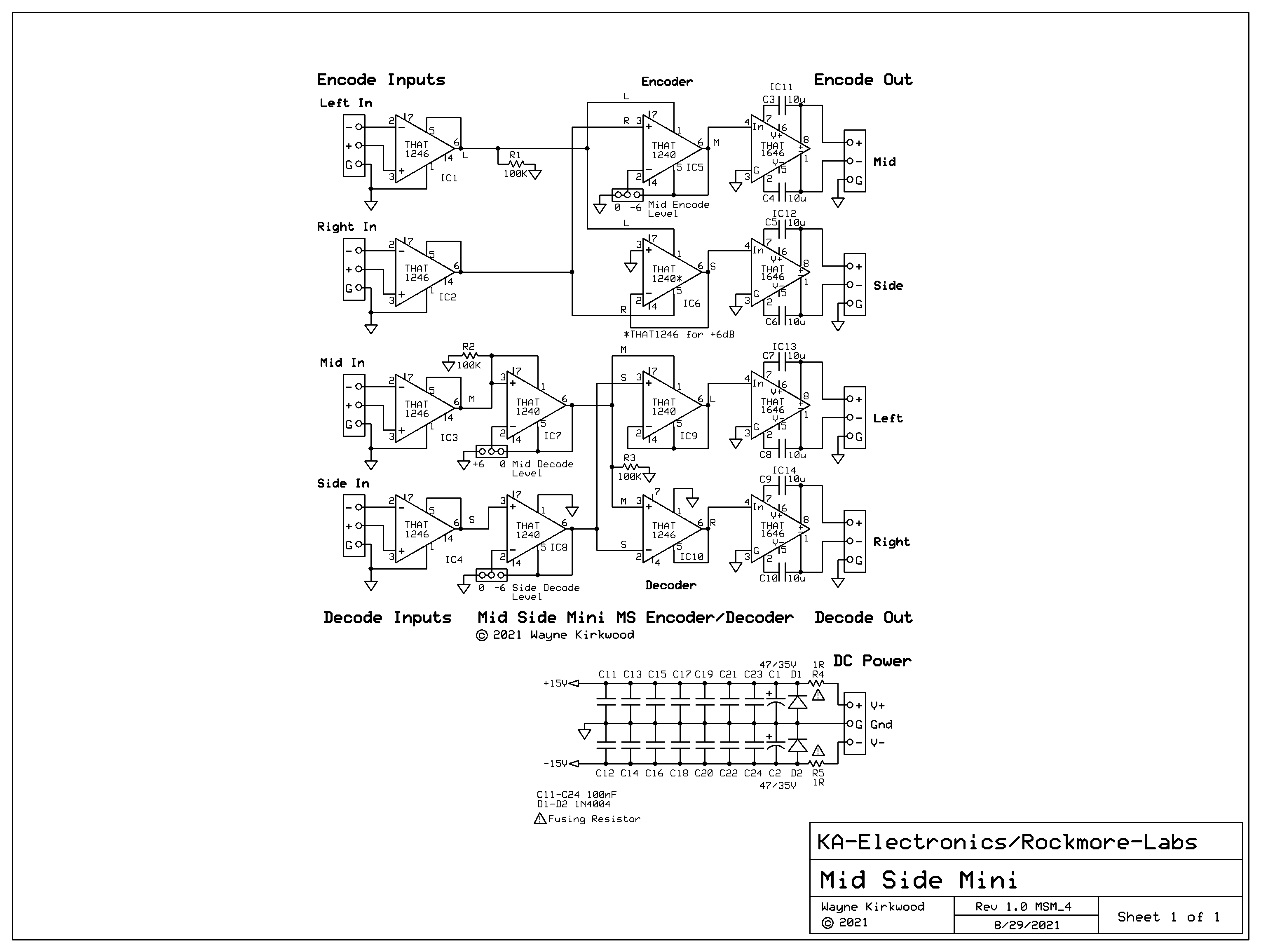
For the 1246 the +27.5 dBu maximum input level is specified with +/-15V supplies.
On the 1646 the +27.5 dBu maximum is specified with +/-18V supplies but that's with a 600Ω load so in practice if the load is bridging the 1646 can usually provide +27.5 dBu with +/-15V and a tad more with +/-18V rails.
I don't see a downside to using +/-18V.
Also, what would be the easiest way to bypass the M/S processing board, to use the unit as L/R? Something like bypass relay wiring of the M/S board + relaying the I/O of the compressor from the M/S I/O to the general I/O? ...so if I'm correct, 4 dpdt relays should do the job?
Maybe an insert switcher board with no Flip and only one insert's worth of relays would be the simplest?
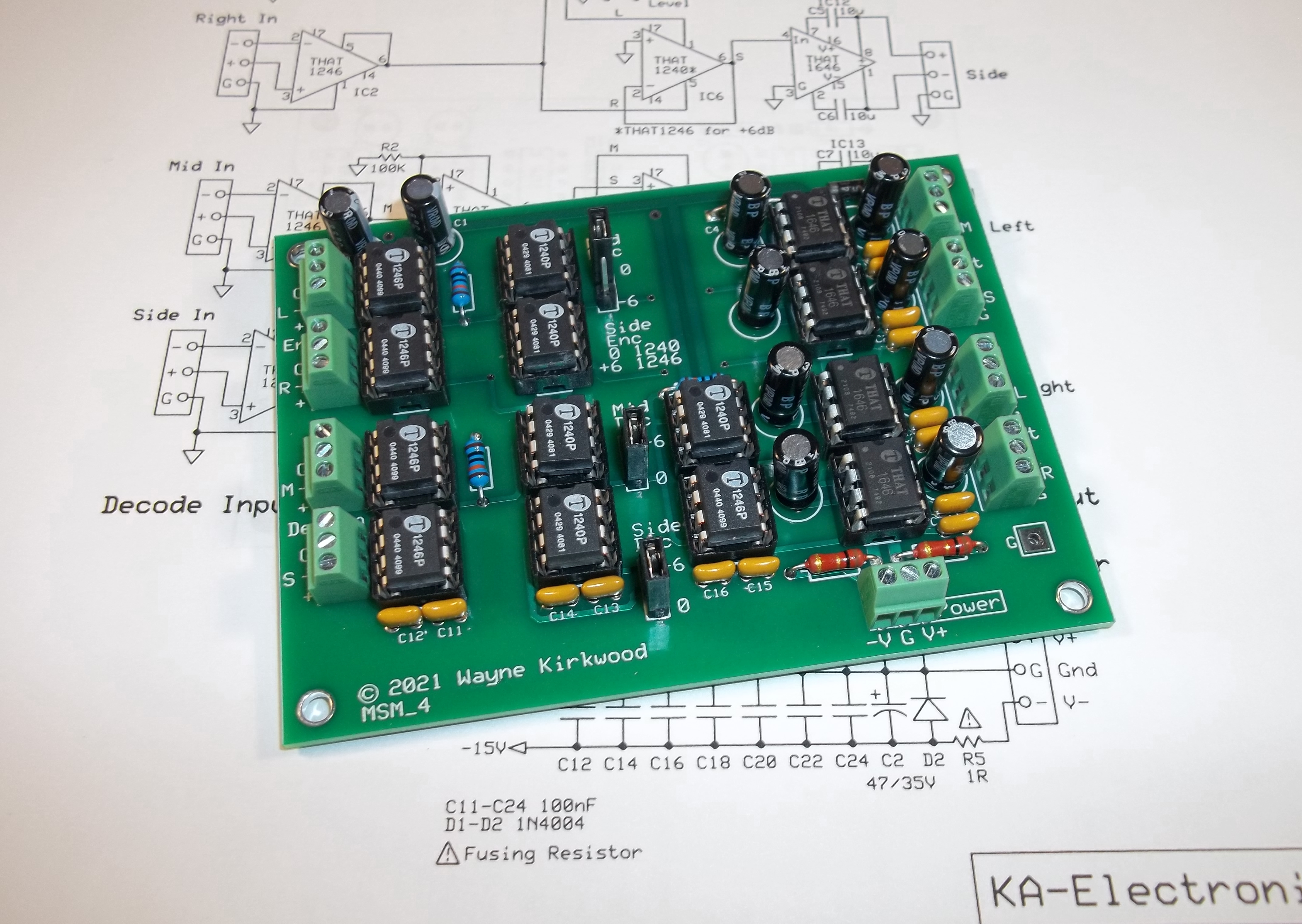
I recall the BOM specifying 35V caps.