A Super-Simple LED Peak Flasher Audio Overload Clipping Indicator Using the TL431
Posted: Sun Apr 29, 2018 5:01 pm
In the "Why didn't I think of this before" category we have a super-simple unipolar peak flasher using the ubiquitous and cheap TL431 shunt regulator as a comparator.
The TL431 is available in a transistor-like TO-92 package for as low as 36 cents each: https://www.mouser.com/ProductDetail/Te ... ysgMLBw%3d
TL431 Datasheet: http://www.ti.com/lit/ds/symlink/tl431a.pdf
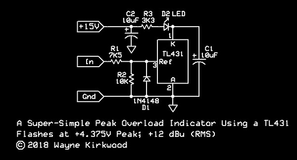
A Super-Simple Peak Flasher/LED Overload Indicator Using the TL431.
The internal reference of the TL431 is 2.5V.
The LED will illuminate when the voltage at pin 3, the Reference input, is greater than 2.5V.
With the values shown, the peak flasher is calibrated to trigger at +4.375V peak based on the voltage-divider formed by R1 and R2.
(4.375V is the peak value of a +12 dBu RMS sine wave.)
R1 and R2's ratios can be adjusted and/or scaled to provide thresholds >2.5V up to tens of volts.
The TL431 and external diode D1 clamp negative-going inputs.
When R2 is open for a threshold of 2.5V, R1 should remain in-circuit to limit input current.
R3 sets the LED current.
C1 acts as a peak hold circuit by delaying LED turn-off.
As with any peak detector, there's a lot of discharge current in the loop formed by C1 and the TL431.
Large ground currents flow so beware in layout.
Without C1 installed switching is very clean without the type of oscillation you'd normally see with an LM339/393-type comparator.
There is a stability boundary area for the TL431 when used as a shunt regulator with feedback.
Values >10 uF or virtually no capacitance at all are acceptable in the Zener configuration.
I don't know if a stability boundary applies in the peak flasher comparator configuration since there is no feedback.
I didn't see any oscillation during switching transitions.
As a practical matter you'll want a big output C1 anyway to make the display persistent.
10 µF seemed about right to my eye for the 4 mA LED current I was using.
It doesn't get much simpler than this: A single 3 pin TO-92 package and you're done.
The detection is unipolar (positive peaks) which for near-overload indication is usually good enough.
Though I haven't tried it I suppose you could use two TL431 on a balanced output and combine the Cathode terminals, "K," for bipolar detection.
For true bipolar detection and gain for detection below 2.5V a single-op amp absolute value circuit could be used ahead of the TL431.
The circuit can also be used as an above-threshold indicator for a compressor.
Performance?
Its fast.
Really, really fast.
With 1 dB overdrive (+13 dBu) the LED stops illuminating around 500 kHz.
At the same level of overdrive, a single-cycle tone burst of 20 kHz will trigger the LED.
The TL431 is normally used as a shunt regulator or "programmable Zener."
For an understanding of how it works as a comparator refer to the TL431 internal block diagram:

When the TL431 is used as a 2.5V reference, the Reference pin and Vout are tied together.
The TL431 acts like a 2.5V Zener.
A voltage divider from Vout to Reference and Ground can be used to scale the output voltage to make it a variable Zener.
In the level detect/comparator configuration there is no feedback.
The reference input is driven directly and the TL431 operates open loop.
When the Reference input is >Vref (2.5V) the output goes low.
Its functionally an LM339/393 comparator with an on-chip reference and only 3 pins.
If you're looking for a simple and easy indicator of signal presence, near clipping or above threshold this simple circuit may fit the bill.
The TL431 is available in a transistor-like TO-92 package for as low as 36 cents each: https://www.mouser.com/ProductDetail/Te ... ysgMLBw%3d
TL431 Datasheet: http://www.ti.com/lit/ds/symlink/tl431a.pdf
A Super-Simple Peak Flasher/LED Overload Indicator Using the TL431.
The internal reference of the TL431 is 2.5V.
The LED will illuminate when the voltage at pin 3, the Reference input, is greater than 2.5V.
With the values shown, the peak flasher is calibrated to trigger at +4.375V peak based on the voltage-divider formed by R1 and R2.
(4.375V is the peak value of a +12 dBu RMS sine wave.)
R1 and R2's ratios can be adjusted and/or scaled to provide thresholds >2.5V up to tens of volts.
The TL431 and external diode D1 clamp negative-going inputs.
When R2 is open for a threshold of 2.5V, R1 should remain in-circuit to limit input current.
R3 sets the LED current.
C1 acts as a peak hold circuit by delaying LED turn-off.
As with any peak detector, there's a lot of discharge current in the loop formed by C1 and the TL431.
Large ground currents flow so beware in layout.
Without C1 installed switching is very clean without the type of oscillation you'd normally see with an LM339/393-type comparator.
There is a stability boundary area for the TL431 when used as a shunt regulator with feedback.
Values >10 uF or virtually no capacitance at all are acceptable in the Zener configuration.
I don't know if a stability boundary applies in the peak flasher comparator configuration since there is no feedback.
I didn't see any oscillation during switching transitions.
As a practical matter you'll want a big output C1 anyway to make the display persistent.
10 µF seemed about right to my eye for the 4 mA LED current I was using.
It doesn't get much simpler than this: A single 3 pin TO-92 package and you're done.
The detection is unipolar (positive peaks) which for near-overload indication is usually good enough.
Though I haven't tried it I suppose you could use two TL431 on a balanced output and combine the Cathode terminals, "K," for bipolar detection.
For true bipolar detection and gain for detection below 2.5V a single-op amp absolute value circuit could be used ahead of the TL431.
The circuit can also be used as an above-threshold indicator for a compressor.
Performance?
Its fast.
Really, really fast.
With 1 dB overdrive (+13 dBu) the LED stops illuminating around 500 kHz.
At the same level of overdrive, a single-cycle tone burst of 20 kHz will trigger the LED.
The TL431 is normally used as a shunt regulator or "programmable Zener."
For an understanding of how it works as a comparator refer to the TL431 internal block diagram:
When the TL431 is used as a 2.5V reference, the Reference pin and Vout are tied together.
The TL431 acts like a 2.5V Zener.
A voltage divider from Vout to Reference and Ground can be used to scale the output voltage to make it a variable Zener.
In the level detect/comparator configuration there is no feedback.
The reference input is driven directly and the TL431 operates open loop.
When the Reference input is >Vref (2.5V) the output goes low.
Its functionally an LM339/393 comparator with an on-chip reference and only 3 pins.
If you're looking for a simple and easy indicator of signal presence, near clipping or above threshold this simple circuit may fit the bill.