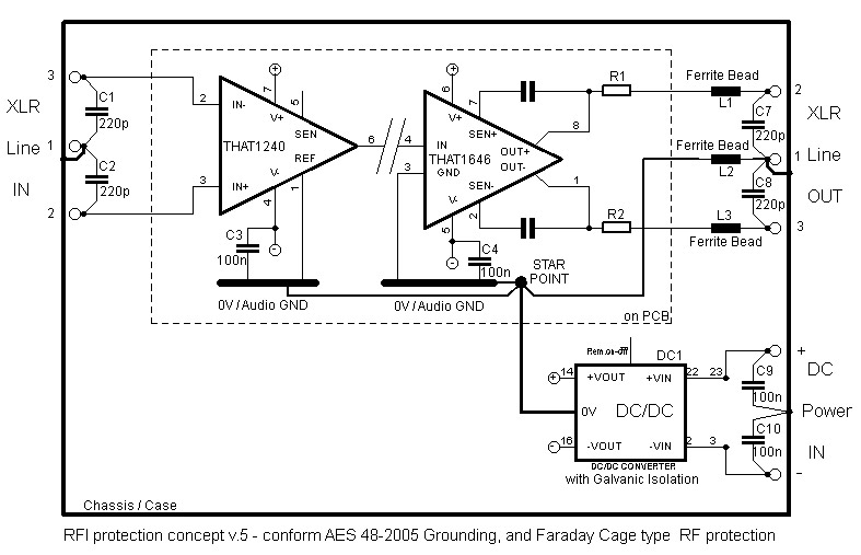
While I have nothing much to add to the RFI discussion, I have opinions about audio references. First I will observe that the pin on the 1246 is labelled "Ref" not GND. I have seen it called 0V and I find that preferable to "audio ground".Gertjan wrote:
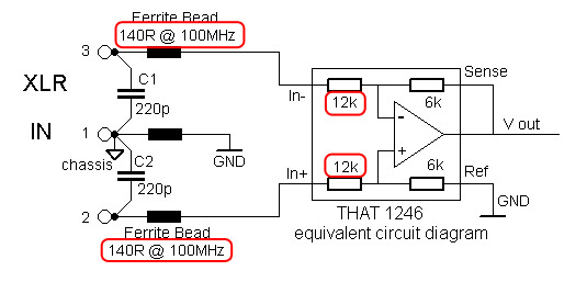
I was looking at the equivalent schematic in the THAT datasheet.
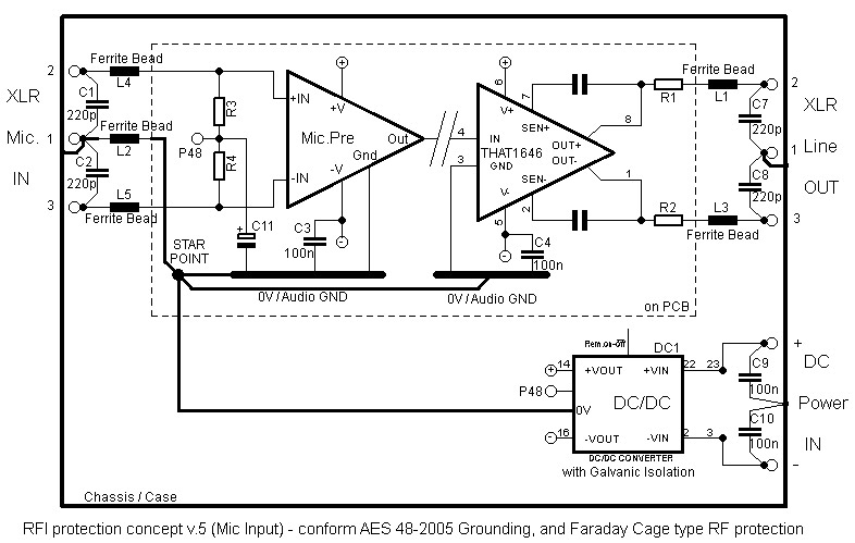
Here is the input redrawn with this equivalent schematic:
First thought is that the Ferrite Bead impedances are small in relation to the THAT input resisters.
But on second thoughts there is off course a lot more in there. Input protection diodes etc.
Maybe enough parasitic capacitance for RF to play with....
I’ll test with input beads in place too.
Regards, Gertjan.
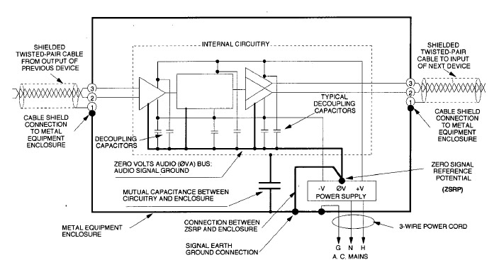
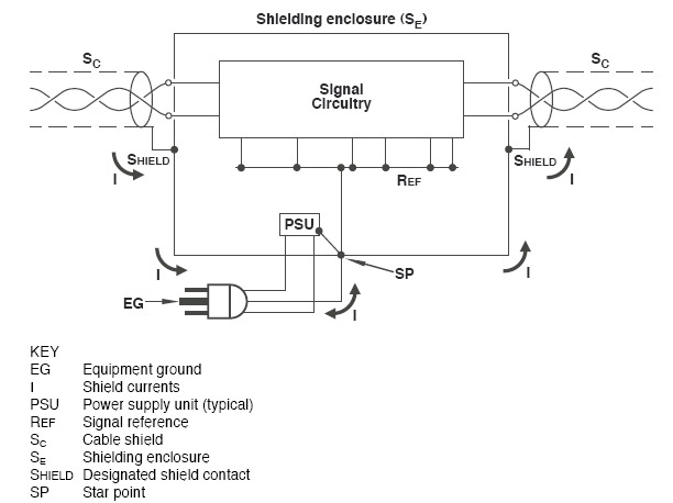
The internal 0V reference generally needs an AC and DC path to PS common, which ideally has an AC and DC path to chassis, but I question the value of hard wire or near hard wire (with FB) connection between 0V and chassis ground. In fact that hard wire connection defeats the benefit of having the differential connection that is working to subtract out ground potential errors.
For large structures I have no problem with having multiple different internal 0V reference nodes, with differential connections to maintain signal integrity between the sundry local references.
The main purpose of providing a path between chassis and PS common, it to keep input common mode signals within the expected PS rail voltages to prevent circuitry saturation. Sometimes when rolling your own output differential circuitry it is tempting to use low value resistors for the reference leg of the differential to provide a modest impedance path too.
Inside the chassis you have audio hot and audio low or audio references. Mixing grounds with signals can be problematic.
JR