Page 6 of 8
Re: Signal generator output ranges
Posted: Sat Mar 30, 2013 7:59 am
by mediatechnology
Thanks for the FB.
Glad I'm not the only one using SMT to DIP adapters for quick prototyping.
Did you by chance do any distortion measurements?
Re: Signal generator output ranges
Posted: Sat Mar 30, 2013 9:54 am
by juniorhifikit
mediatechnology wrote:Did you by chance do any distortion measurements?
Unfortunately no. I was just looking at my scope for clipping. I
did do a full 20Hz - 20KHz sweep though. I don't really have anything official for distortion measurements other than RMAA through my converters, which wasn't really practical in this situation.
Re: Signal generator output ranges
Posted: Mon Apr 08, 2013 9:32 am
by mediatechnology
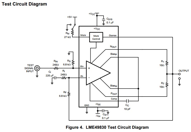
Though it appears to have a Vce sat of around 5V the LME49830 is also a nice HV output stage. Vcc-Vee can be up to 200V.
http://www.ti.com/product/LME49830
Re: Signal generator output ranges
Posted: Mon Apr 08, 2013 10:53 am
by JR.
Knowing what it cost to develop an IC makes that application seem odd... even more expensive to handle 200V rails. I have to wonder if they are approaching this backwards, having the 200V process and looking for an application that fits the process, rather than responding to a market need or demand. National had a high voltage amp front end back in the 80s and I don't recall very many design ins .
Back a few decades ago while working at Peavey we investigated and actually started a project to make an IC to handle a standard power amp front end with some useful glue (built in clip limiter). Peavey made and sold lots of channels of audio amplification ranging from 35W to several hundred Watts. We even had a topology that worked in standard IC process voltages (<36V) so much cheaper than that 200V design. Unfortunately the IC company (or junior engineer) we were working with couldn't deliver on a well behaved LTP to integrate an effective OTA into the IC (He suggested adding a degeneration resistors to the LTP in an OTA.

Clearly no understanding of how OTAs work. That's when our project fell apart.)
Looking at the mute for the 49830 it looks like they are pulling the output to - supply. While block diagram may not be literal description of what is going on.
JR
Re: Signal generator output ranges
Posted: Tue Apr 16, 2013 2:03 pm
by mediatechnology
The Electronic Design insert from Linear Technology this month features applications for the LTC6090 high voltage op amp.
Linear Technology Design Note 513:
http://cds.linear.com/docs/en/design-note/dn513f.pdf
The 9V to +/-65V boost converter in Figure 2 in caught my attention.
Unfortunately it uses a non-standard Midcom/Wurth Electronics transformer but it looks like the LT8300 can be paired with stock magnetics to obtain either +/-15V or 48V.
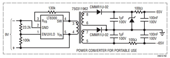 LT8300 9V to +/-65V Boost Converter
Linear Technology LT8300
http://cds.linear.com/docs/Datasheet/8300f.pdf
Wurth Electronics:
http://www.we-online.com/web/en/passive ... ormers.php
Re: Signal generator output ranges
Posted: Thu Apr 25, 2013 2:38 pm
by mediatechnology
Here's another booster stage that I had forgotten about using readily-available components.
No need to use the OP37. I'd like to try it with modern parts.
This one swings within about 1V of either rail.
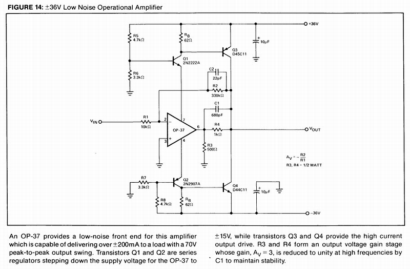 Op Amp Booster Stage +/-36V Analog Devices AN-106
Re: Signal generator output ranges
Posted: Thu Apr 25, 2013 3:03 pm
by juniorhifikit
Thanks Wayne! Another nice tool for the tool kit.
Re: Signal generator output ranges
Posted: Thu Apr 25, 2013 5:30 pm
by mediatechnology
I built the circuit with some minor modifications.
With +/-31.5V supplies I can get just under +29 dBu, ~22 Vrms.
I used an LME49710 and a BD139/BD140 pair.
I increased Rb to 120R to eliminate HF crossover distortion.
If I get a chance I'll tweak the AC performance, post the sch, and run some THD tests.
The Cc values they show aren't optimal.
Re: Boosting signal generator or op amp outputs to >+30 dBu
Posted: Sat Apr 27, 2013 11:04 am
by mediatechnology
I've made some more improvements to the +/-36V booster shown in the previous posts.
Still tweaking...
This application note, originally from Burr-Brown, provides some insight into the previous circuit:
http://www.ti.com/lit/an/sboa009/sboa009.pdf
As shown, the output is only boosted to improve the output voltage swing to provide almost rail-to-rail performance.
Note how feedback is locally returned to the INA105
output.
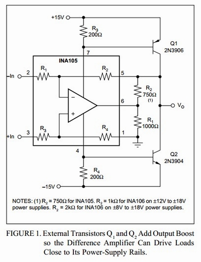 INA105 with voltage-boosted output to provide almost rail-to-rail performance
TI Application Note SBOA009
This circuit fragment shows how current feedback is returned from the boosted output into the INA105's output stage emitter.
"Q3" is the top output transistor internal to the INA105.
Note how this is virtually identical to the +/-36V output stage shown earlier.
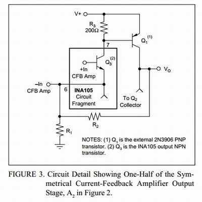 INA105 shown with current feedback returned to the output stage emitters.
TI Application Note SBOA009
I also have an SSM application note for a power amplifier using the same trick that I'll post later.
That circuit uses a unique DC servo.
Re: Boosting signal generator or op amp outputs to >+30 dBu
Posted: Mon Apr 29, 2013 10:54 am
by mediatechnology
Well, the circuit below can certainly swing +30 dBu but I'd call it a Class-B output stage.
Unloaded THD is quite good but unless it's idled >>50 mA there is cross-over distortion under load.
The Q-point stability is not that good when biased for Class-AB performance.