Jeff - Thanks for joining us!
I haven't done an M-101 alignment but I think I have some printed notes from an email by someone who has.
I'll dig for them.
Texar Audio Prism Schematics and Information
-
mediatechnology

- Posts: 5466
- Joined: Sat Aug 11, 2007 2:34 pm
- Location: Oak Cliff, Texas
- Contact:
-
mediatechnology
- Posts: 5466
- Joined: Sat Aug 11, 2007 2:34 pm
- Location: Oak Cliff, Texas
- Contact:
Re: Texar Audio Prism Schematics and Information
flyboy71 sent me a post made by Glen Clark on another forum where he describes some of the production modifications and upgrades made to the Texar Audio Prism. Thanks for sending this Jeff!
Texar Audio Prism Service Glen Clark's Post: https://proaudiodesignforum.com/images/ ... k_Post.pdf
Texar Audio Prism Service Glen Clark's Post: https://proaudiodesignforum.com/images/ ... k_Post.pdf
-
mediatechnology
- Posts: 5466
- Joined: Sat Aug 11, 2007 2:34 pm
- Location: Oak Cliff, Texas
- Contact:
Refurbishing the Texar Audio Prism
I just finished refurbishing a pair of the Texar Audio Prisims that I've had "in waiting: since 2015.

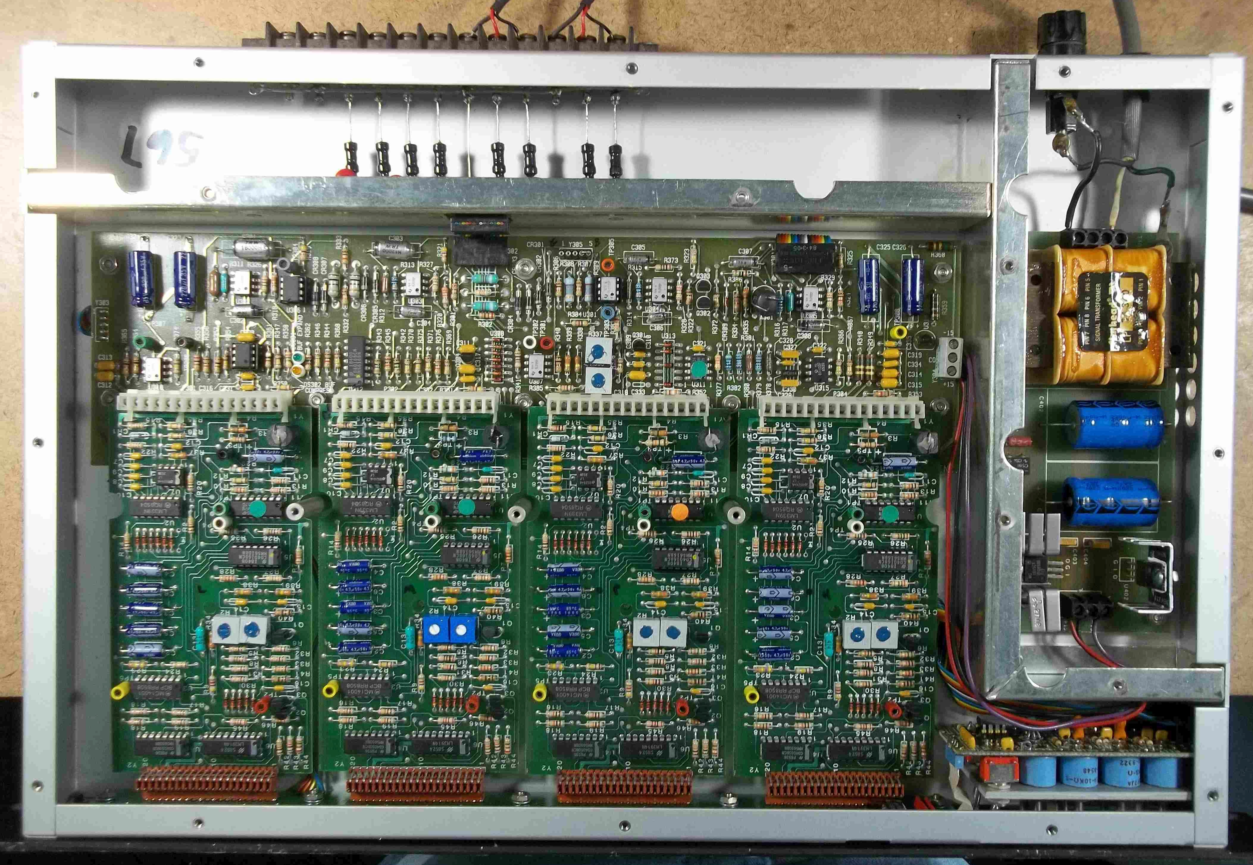
Texar Audio Prisims on the workbench...
The first repair I made was back in 2015 to cure "Molexia" intermittents. https://proaudiodesignforum.com/forum/p ... 764&p=8965
Molexia are the solder ring cracks that form around round Molex pins.
The Texar had quite a few which caused many intermittents.

Solder connections to round Molex pins develop crystallized microscopic ring cracks around the pin over time that must be resoldered.
I revisted the project this week and, based on the sonic results, I'm glad I did. Fast-forward to September 2020:
I did a full electrolytic recap which involved replacing all the 4.7 µF axial caps on the M-101 boards, 4 220 µF caps on the main board and 2 2200 µF caps in the power supply.
It should be noted that the Texar has no electrolytics in the signal path - all of the 4.7 µF caps are in the sidechain and control sections.
The 220 and 2200 µF caps are power supply bypass and bulk filtering.
Most of the 4.7 µF removed were reading about 30-40% low.
The filter and bypass caps were actually in tolerance.
Not bad for a 1986 unit that runs hot.
I also replaced the whimpy 28G ribbon cable leads from the power supply output to the main board.
These lines carry the full operating current for the unit which includes all the LED current for 40 LEDs.

Texar Audio Prism Power Supply
One of the bulk filter caps, C401 had a 0.1 µF axial lead monolithic ceramic cap installed underneath it wrapped around the electrolytic's leads.
This was presumably to reduce the possibility of the regulator oscillating.
I installed a radial lead 100 nF monolythic ceramic at the regulator terminals on both the positive and negative regulators underneath the board.
On the M-101 boards I checked the sidechain/Vactrol calibration which involves removing a CD4016, shorting pins on the 4016's socket and reading levels at a resistor lead. (See: https://www.proaudiodesignforum.com/ima ... gnment.pdf )
Note that step 18 doesn't give a dB value - I think it's -9 or -10 dBu.
All but one of the 8 boards passed calibration tests which is a good thing considering that the trims are glued in place and the Vactrols virtually unobtainable.
Fortunately I bought a stock of VTL5C3 while they were still available and used one to repair the board which had aged out of limit.
That board required trimmer replacement and adjustment went fairly easy.

Texar Audio Prism M101 Board
I was not the first person who apparently checked calibration and following the suggestion to use bus wire to link the socket pins is not a good idea.
About 3 of the 8 cards' IC sockets for the 4016s were intermittent so I replaced all 8.
The sockets seemed to have low contact force and were a single beam type.
I didn't have enough dual beam high insertion force sockets so I used some nice machine pin versions.
I'm going to make a test jig with a proper male 14 pin header to keep from damaging the new ones.
These units were operated as a stereo pair but I found one of them had a misadjusted bypass gain trimmer, R115, which took some effort to find.
It's hidden behind the front panel and is one of the few front panel trims for which there is no access hole.

Texar Audio Prism CX-1 Board.
R115 is hidden between the two red toggle switches.
The sub panel has an access hole for R115 but to get to it the front panel has to be removed.
The one thing I haven't done is replace the input differential stage with an OPA2134.
Both the input IC and 5532 output are socketed.
Glen Clarke was very concerned about lightning damage and made sure those exposed ICs were easily field replaceable.
Balancing the two units' Mix controls for the four bands is easily done using a scope in X-Y mode and inputting mono tones at the band centers.
I haven't tried using pink noise yet.
I tried using stereo coupling and decided to follow Glen's advice and ultimately removed it.
Elements panned center stay centered without it and the width enhancement you get for elements panned off-center is very pleasing.
Texar Audio Prism
I'm really happy with the sound of these units after the TLC refurb.
They deserve all the credit they've received over the years and do sound just like I remember them at KTXQ/Q102 in Dallas in the late 80's and 90's when they were running ahead of the Optimod 8100.
They do a great job at unintrusive level normalization for the music collection and add a lot of life to dull-sounding older material with their unique spectral loading/dynamic EQ effect.
They'll be running in my background music playback system around the house.
Texar Audio Prisims on the workbench...
The first repair I made was back in 2015 to cure "Molexia" intermittents. https://proaudiodesignforum.com/forum/p ... 764&p=8965
Molexia are the solder ring cracks that form around round Molex pins.
The Texar had quite a few which caused many intermittents.
Solder connections to round Molex pins develop crystallized microscopic ring cracks around the pin over time that must be resoldered.
I revisted the project this week and, based on the sonic results, I'm glad I did. Fast-forward to September 2020:
I did a full electrolytic recap which involved replacing all the 4.7 µF axial caps on the M-101 boards, 4 220 µF caps on the main board and 2 2200 µF caps in the power supply.
It should be noted that the Texar has no electrolytics in the signal path - all of the 4.7 µF caps are in the sidechain and control sections.
The 220 and 2200 µF caps are power supply bypass and bulk filtering.
Most of the 4.7 µF removed were reading about 30-40% low.
The filter and bypass caps were actually in tolerance.
Not bad for a 1986 unit that runs hot.
I also replaced the whimpy 28G ribbon cable leads from the power supply output to the main board.
These lines carry the full operating current for the unit which includes all the LED current for 40 LEDs.
Texar Audio Prism Power Supply
One of the bulk filter caps, C401 had a 0.1 µF axial lead monolithic ceramic cap installed underneath it wrapped around the electrolytic's leads.
This was presumably to reduce the possibility of the regulator oscillating.
I installed a radial lead 100 nF monolythic ceramic at the regulator terminals on both the positive and negative regulators underneath the board.
On the M-101 boards I checked the sidechain/Vactrol calibration which involves removing a CD4016, shorting pins on the 4016's socket and reading levels at a resistor lead. (See: https://www.proaudiodesignforum.com/ima ... gnment.pdf )
Note that step 18 doesn't give a dB value - I think it's -9 or -10 dBu.
All but one of the 8 boards passed calibration tests which is a good thing considering that the trims are glued in place and the Vactrols virtually unobtainable.
Fortunately I bought a stock of VTL5C3 while they were still available and used one to repair the board which had aged out of limit.
That board required trimmer replacement and adjustment went fairly easy.
Texar Audio Prism M101 Board
I was not the first person who apparently checked calibration and following the suggestion to use bus wire to link the socket pins is not a good idea.
About 3 of the 8 cards' IC sockets for the 4016s were intermittent so I replaced all 8.
The sockets seemed to have low contact force and were a single beam type.
I didn't have enough dual beam high insertion force sockets so I used some nice machine pin versions.
I'm going to make a test jig with a proper male 14 pin header to keep from damaging the new ones.
These units were operated as a stereo pair but I found one of them had a misadjusted bypass gain trimmer, R115, which took some effort to find.
It's hidden behind the front panel and is one of the few front panel trims for which there is no access hole.
Texar Audio Prism CX-1 Board.
R115 is hidden between the two red toggle switches.
The sub panel has an access hole for R115 but to get to it the front panel has to be removed.
The one thing I haven't done is replace the input differential stage with an OPA2134.
Both the input IC and 5532 output are socketed.
Glen Clarke was very concerned about lightning damage and made sure those exposed ICs were easily field replaceable.
Balancing the two units' Mix controls for the four bands is easily done using a scope in X-Y mode and inputting mono tones at the band centers.
I haven't tried using pink noise yet.
I tried using stereo coupling and decided to follow Glen's advice and ultimately removed it.
Elements panned center stay centered without it and the width enhancement you get for elements panned off-center is very pleasing.
Texar Audio Prism
I'm really happy with the sound of these units after the TLC refurb.
They deserve all the credit they've received over the years and do sound just like I remember them at KTXQ/Q102 in Dallas in the late 80's and 90's when they were running ahead of the Optimod 8100.
They do a great job at unintrusive level normalization for the music collection and add a lot of life to dull-sounding older material with their unique spectral loading/dynamic EQ effect.
They'll be running in my background music playback system around the house.
-
mediatechnology
- Posts: 5466
- Joined: Sat Aug 11, 2007 2:34 pm
- Location: Oak Cliff, Texas
- Contact:
Texar Audio Prism Hum Reduction
Once the refurbishment was complete with new PSU caps I decided to listen to the noise floor which is dominated by some nasty hum.
The FFTs are not that great.
The solution to the source of the hum provides an interesting story and power supply life-lesson.
This is the Texar's unmodified FFT:
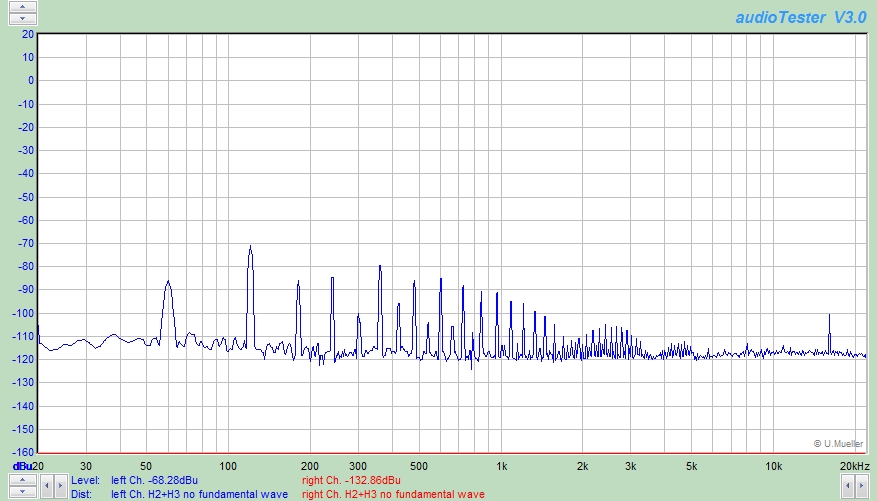
Unmodified Texar Audio Prism hum.
Yikes!
My suspicion is that the power supply, which measures electrically quiet, is radiating a bodacious magnetic flux field.
This likely explains why Gentner, when they bought the design from Texar, switched to a toroidal transformer.
I decided to see just how quiet the unit would be if run from an external bench supply:

Texar hum running on an external bench supply.
Good enough! I'll take that.
The next test involved running it from the bench supply but powering the internal supply with no load attached.
The Texar powered by an external supply with the internal supply on but unloaded.
OK, it's still pretty good.
This tells me that its related to the load current and the resulting flux field inducing hum into cabling and the PC board.
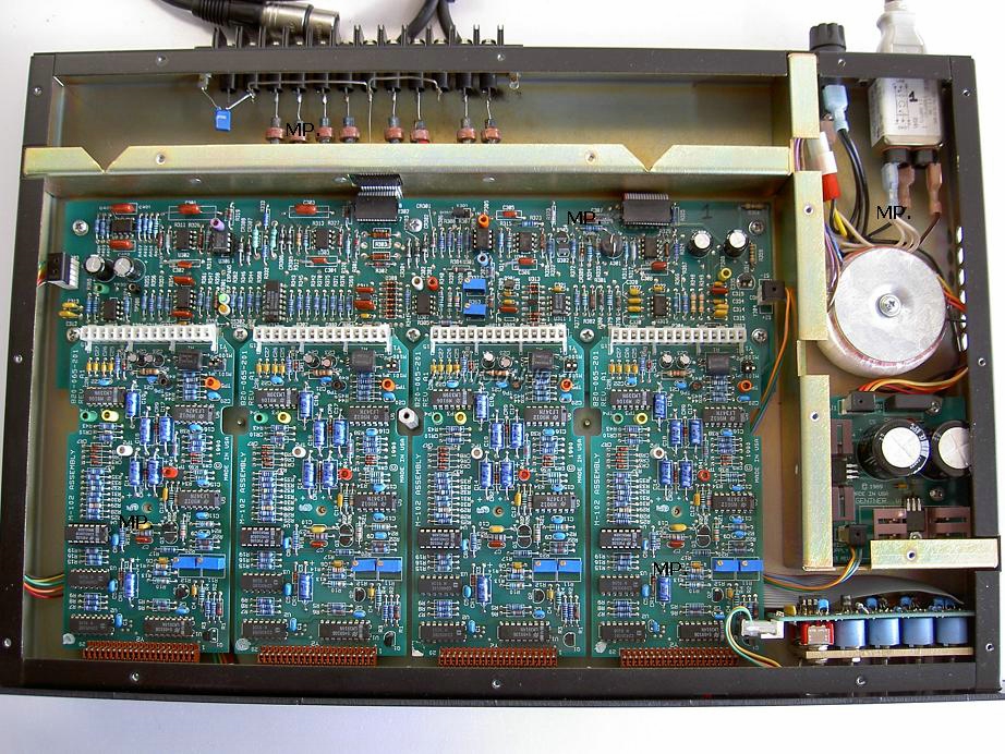
I decided to re-route the ribbon cable from the MB-2 motherboard to the CX-2 board which runs parallel to the PSU cage and use the internal supply.

Texar Audio Prisim ribbon cable re-routed.
I took a quick look at the Gentner version of the Texar and they also apparently figured out that the ribbon cable was too close to the transformer.
( https://proaudiodesignforum.com/images/ ... _Prism.jpg )
The odd-order harmonic content is reduced considerably:

The Texar powered from its internal supply with a re-routed ribbon cable.
Re-routing the ribbon cable helps some.
Now, most of the odd-order hum is third harmonic and it's reduced from about -85 to -100 dBu.
But look at how much even-order remains!
This provides a clue...
The Texar's LED load is drawn from the positive supply.
The average operating current, measured while it was on the bench supply, was about 90 mA on the negative but 350-400 mA on the positive.
Unequally loaded split supplies (sharing a common bridge rectifier) cause DC current in the windings and magnetic circuit.
The transformer is rated at 340 mA and the DC in the magnetic circuit is saturating the core.
The saturated core, which is only saturated on the positive half-cycle, explains the large amount of even high-order flux-induced hum.
The magnetic circuit is "clipping" and producing high-order harmonics.
Transformers with DC in them also tend to run hotter.
Here's where things get counter-intuitive...
I decided to load the negative supply, at the filter cap, with an additional 200 mA (approximate) to balance the load and eliminate the core DC.
Does it work?

Yes!
This is not the ideal solution because the added load, which consumes an additional 4W, now lowers the transformer output voltage and low-line performance.
Prior to added loading the positive unregulated rail ran about 20.5 VDC and the negative about -22 VDC.
They are both now about 19V each.
The regulators drop out of regulation around 115 VAC instead of about 105.
This exercise teaches a valuable lesson: Avoid grossly unbalanced loads on split supplies particularly when the transformer is running at or above its' maximum current rating.
I'm going to explore running the TDK CUT35 switcher in the Texar...
https://proaudiodesignforum.com/forum/p ... 29&#p11129
The FFTs are not that great.
The solution to the source of the hum provides an interesting story and power supply life-lesson.
This is the Texar's unmodified FFT:
Unmodified Texar Audio Prism hum.
Yikes!
My suspicion is that the power supply, which measures electrically quiet, is radiating a bodacious magnetic flux field.
This likely explains why Gentner, when they bought the design from Texar, switched to a toroidal transformer.
I decided to see just how quiet the unit would be if run from an external bench supply:
Texar hum running on an external bench supply.
Good enough! I'll take that.
The next test involved running it from the bench supply but powering the internal supply with no load attached.
The Texar powered by an external supply with the internal supply on but unloaded.
OK, it's still pretty good.
This tells me that its related to the load current and the resulting flux field inducing hum into cabling and the PC board.
I decided to re-route the ribbon cable from the MB-2 motherboard to the CX-2 board which runs parallel to the PSU cage and use the internal supply.
Texar Audio Prisim ribbon cable re-routed.
I took a quick look at the Gentner version of the Texar and they also apparently figured out that the ribbon cable was too close to the transformer.
( https://proaudiodesignforum.com/images/ ... _Prism.jpg )
The odd-order harmonic content is reduced considerably:
The Texar powered from its internal supply with a re-routed ribbon cable.
Re-routing the ribbon cable helps some.
Now, most of the odd-order hum is third harmonic and it's reduced from about -85 to -100 dBu.
But look at how much even-order remains!
This provides a clue...
The Texar's LED load is drawn from the positive supply.
The average operating current, measured while it was on the bench supply, was about 90 mA on the negative but 350-400 mA on the positive.
Unequally loaded split supplies (sharing a common bridge rectifier) cause DC current in the windings and magnetic circuit.
The transformer is rated at 340 mA and the DC in the magnetic circuit is saturating the core.
The saturated core, which is only saturated on the positive half-cycle, explains the large amount of even high-order flux-induced hum.
The magnetic circuit is "clipping" and producing high-order harmonics.
Transformers with DC in them also tend to run hotter.
Here's where things get counter-intuitive...
I decided to load the negative supply, at the filter cap, with an additional 200 mA (approximate) to balance the load and eliminate the core DC.
Does it work?
Yes!
This is not the ideal solution because the added load, which consumes an additional 4W, now lowers the transformer output voltage and low-line performance.
Prior to added loading the positive unregulated rail ran about 20.5 VDC and the negative about -22 VDC.
They are both now about 19V each.
The regulators drop out of regulation around 115 VAC instead of about 105.
This exercise teaches a valuable lesson: Avoid grossly unbalanced loads on split supplies particularly when the transformer is running at or above its' maximum current rating.
I'm going to explore running the TDK CUT35 switcher in the Texar...
https://proaudiodesignforum.com/forum/p ... 29&#p11129
-
mediatechnology
- Posts: 5466
- Joined: Sat Aug 11, 2007 2:34 pm
- Location: Oak Cliff, Texas
- Contact:
Re: Texar Audio Prism Schematics and Information
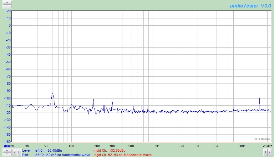
The TDK CUT35 switcher measures significantly quieter than the internal supply.
Updated 9/22/20. I got two more TDK switchers from Mouser today and have properly-fitted the power supplies with connectorized leads. I can now show the noise floor of a stereo pair.

Texar Audio Prism noise floor using the TDK CUT35 switching power supply.
The 240 Hz peak is interesting.
Note the difference in frequency between channels suggesting that the switchers are operating at slightly different frequencies.
I tried investigate the source of this spur and don't see it in the audio supply lines.
The 5V supply, which has it's own isolated ground and converter IC, is unloaded.
While the 5V could have been operating in hiccup mode pre-loading doesn't seem to make a difference.
I think the spurs may be magnetic and induced into unshielded audio lines leading to the CX-2 board in the Texar.
I've used the TDK switcher with several of my boards and never have noticed these 240 Hz spurs.
It seems unique to the Texar which uses some really high impedance internal circuitry.
Nevertheless the Texar now measures about -80 dBu which is much quieter than the -68 dBu with the magnetically-saturated linear supply.
This is what the Texar's noise floor looked like before:
Unmodified Texar Audio Prism hum.

The Texar with a TDK CUT35 switcher fitted in the existing power supply compartment.
The unit will certainly run cooler...
More info on the TDK switcher:
TDK-Lambda 35W 5V 3A, +/-15V +1A/-650 mA switching supply CUT35-5FF.
Mouser CUT35-5FF product page: https://www.mouser.com/ProductDetail/TD ... TIWQ%3d%3d
TDK CUT35 datasheet: https://www.mouser.com/ds/2/400/cut35-1101382.pdf
Mouser Project Manager for TDK CUT355FF power supply and mating connectors/pins: https://www.mouser.com/ProjectManager/P ... 65b59a493a
Updated 9/22/20. I got two more TDK switchers from Mouser today and have properly-fitted the power supplies with connectorized leads. I can now show the noise floor of a stereo pair.
Texar Audio Prism noise floor using the TDK CUT35 switching power supply.
The 240 Hz peak is interesting.
Note the difference in frequency between channels suggesting that the switchers are operating at slightly different frequencies.
I tried investigate the source of this spur and don't see it in the audio supply lines.
The 5V supply, which has it's own isolated ground and converter IC, is unloaded.
While the 5V could have been operating in hiccup mode pre-loading doesn't seem to make a difference.
I think the spurs may be magnetic and induced into unshielded audio lines leading to the CX-2 board in the Texar.
I've used the TDK switcher with several of my boards and never have noticed these 240 Hz spurs.
It seems unique to the Texar which uses some really high impedance internal circuitry.
Nevertheless the Texar now measures about -80 dBu which is much quieter than the -68 dBu with the magnetically-saturated linear supply.
This is what the Texar's noise floor looked like before:
Unmodified Texar Audio Prism hum.
The Texar with a TDK CUT35 switcher fitted in the existing power supply compartment.
The unit will certainly run cooler...
More info on the TDK switcher:
TDK-Lambda 35W 5V 3A, +/-15V +1A/-650 mA switching supply CUT35-5FF.
Mouser CUT35-5FF product page: https://www.mouser.com/ProductDetail/TD ... TIWQ%3d%3d
TDK CUT35 datasheet: https://www.mouser.com/ds/2/400/cut35-1101382.pdf
Mouser Project Manager for TDK CUT355FF power supply and mating connectors/pins: https://www.mouser.com/ProjectManager/P ... 65b59a493a
Re: Texar Audio Prism Schematics and Information
Did you perform the M101 alignment per that procedure earlier in the thread? Im pretty sure all my Vactrols are aged out of spec because the calibration resistance per the procedure was almost 30k and it still wasnt close. This is assuming I wasnt doing something wrong. I guess my first question is whether the alignment procedure should be edited a bit. I do know I have far too much mid band response so I doubt seriously its compressing anywhere close to the -20dB spec. Maybe I can tackle it again this winter when everyone is stuck home under a politically induced quarantine again.
My projects site: https://ornerscorner.neocities.org/
"Things are more like they are now then they ever were before" - Dwight
"Things are more like they are now then they ever were before" - Dwight
-
mediatechnology
- Posts: 5466
- Joined: Sat Aug 11, 2007 2:34 pm
- Location: Oak Cliff, Texas
- Contact:
Re: Texar Audio Prism Schematics and Information
Hey flyboy71 it's been awhile...
The series resistor was 9K09 with the one Vactrol I replaced.On the M-101 boards I checked the sidechain/Vactrol calibration which involves removing a CD4016, shorting pins on the 4016's socket and reading levels at a resistor lead. (See: https://www.proaudiodesignforum.com/ima ... gnment.pdf )
Note that step 18 doesn't give a dB value - I think it's -9 or -10 dBu.
All but one of the 8 boards passed calibration tests which is a good thing considering that the trims are glued in place and the Vactrols virtually unobtainable.
Fortunately I bought a stock of VTL5C3 while they were still available and used one to repair the board which had aged out of limit.
That board required trimmer replacement and adjustment went fairly easy.
-
mediatechnology
- Posts: 5466
- Joined: Sat Aug 11, 2007 2:34 pm
- Location: Oak Cliff, Texas
- Contact:
Re: Texar Audio Prism Schematics and Information
Looks like CE Distribution is now stocking the XVive VTL5C3 "Vactrols" used on the M101 boards.
https://www.cedist.com/products/optocou ... l5c-series
https://www.cedist.com/products/optocou ... l5c-series