Vintage Digital Clock Circuits

A resource for technical documentation. Datasheets, application notes, instruction manuals, books and links to resources are found in the Document Library.
User avatar
mediatechnology
Posts: 5437
Joined: Sat Aug 11, 2007 2:34 pm
Location: Oak Cliff, Texas
Contact:

Re: Vintage Digital Clock Circuits

Post by mediatechnology »

Some ZM-1000 driver experiments...

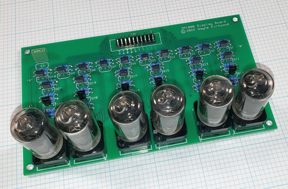
I got some BS107 N-CH MOSFETs and tested them with a ZM-1000 tube.
Unfortunately the BS107 has too much off-state leakage and causes some cathode glow.
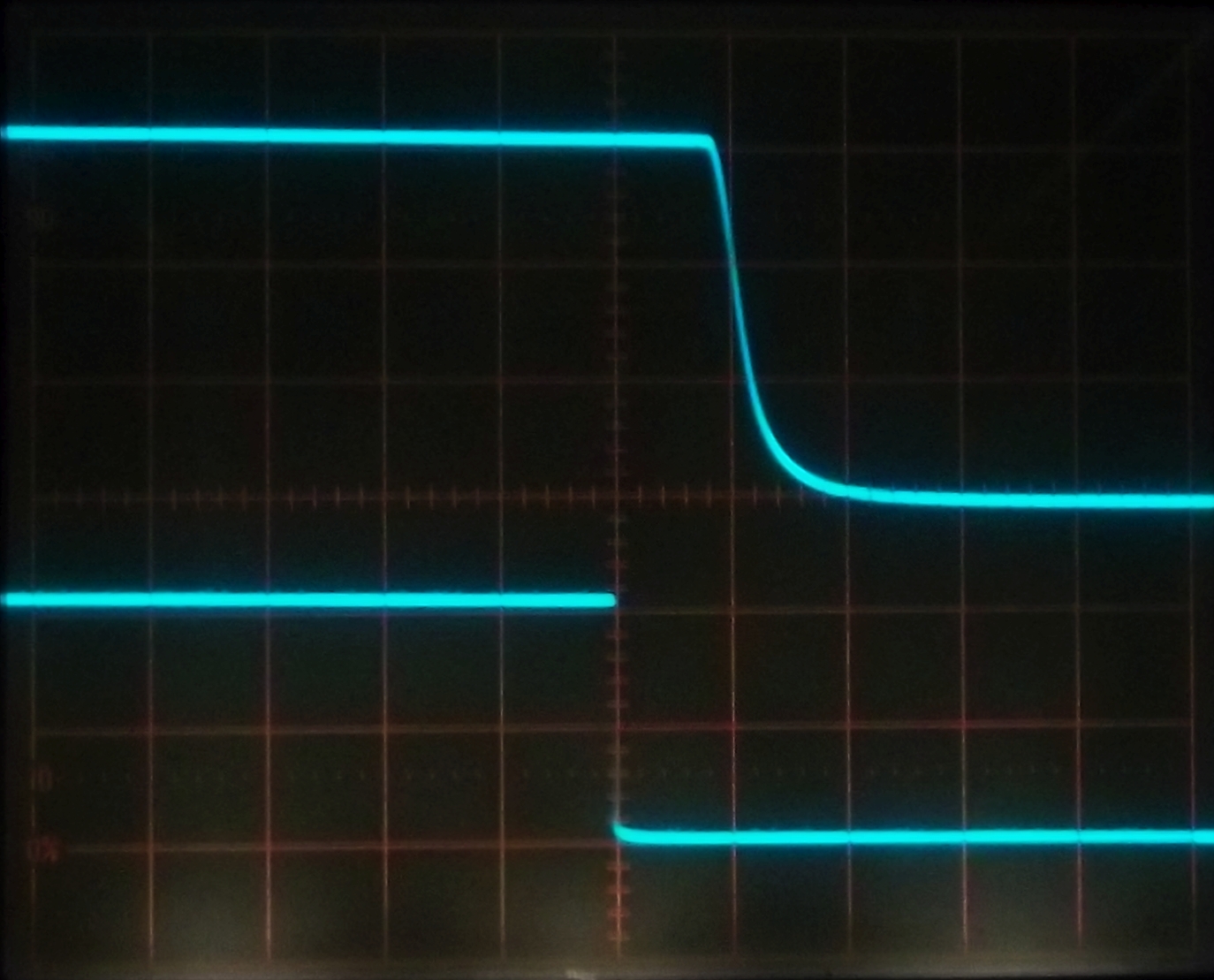
I substituted the BS170 which previously worked and found that with this particular tube there was also some cathode glow as well even when the Drain is clamped at around 65V.

What also may be different is the power supply.
This experiment was made with a 555-based switcher - it could be that the large amount of ripple in my original HV supply dropped below the strike voltage of the tube.

With the switcher the MPSA42 300V NPN worked fine so it looks like MOSFETs and clamped LV bipolars such as the ULN2003 are risky with certain tubes or supplies.
I also played around with a muxed display approach and tried a classic MPSA92/MPSA42 PNP/NPN anode driver.

The more I think about it the more I like using an Arduino Nano and DS-series RTC board.
With a single 8 bit port I can mux anode and cathode drive for a 6 digit clock.

This is the classic NE555/IRF740-based flyback converter needed to get the +170V needed for the anodes.
It works pretty well being about 80-85% efficient and offers OK regulation.

Image

Note that P1 is correctly-drawn.
In many of the schematics for this circuit the wiper and top of the pot are not connected to each other.
With the base circuit connected directly to the wiper loss of wiper contact causes the supply to run open loop, lose all regulation and go to the maximum output voltage.
User avatar
mediatechnology
Posts: 5437
Joined: Sat Aug 11, 2007 2:34 pm
Location: Oak Cliff, Texas
Contact:

Multiplexing the ZM1000 Nixie Tube - Drivers and Waveforms

Post by mediatechnology »

Now that I've decided to multiplex the ZM1000 Nixies I wanted to check some of the online assumptions many have made regarding drivers and refresh rates.

I used the test circuit below and either tied the cathode drive to +V for Anode multiplexing or the Anode lead to V+ to test cathode driving. A pulse generator is used to control the other input.

The ZM1000 has a 12 mA maximum Anode current. For a display with 6 multiplexed digits the average current is approximately 2 mA. The datasheet list a 2.5 mA maximum average current. I decided to use 8-10 mA with 10 mA having a 1.66 mA average current. The currents will be slightly less when inter digit blanking is included.

Image
ZM1000 Pulse Operation

The 100Ω resistor in digit 8 serves as a shunt to measure cathode current indirectly.
The transistor has about 100 mV of Vsat so the voltage across the 100Ω, minus 100 mV, is an indication of anode/cathode current.

Image
ZM1000 Multiplex Test Circuit

The following is the anode driver waveform versus cathode current. The peak current is just under 10 mA.

Image
ZM1000 Anode Driver Waveform Anode CH-A 50V-Div, Cathode Current CH-B 5mA-Div, 500us-Div

Most anode driver circuits I've seen using the MPSA42/MPSA92 have too high base-emitter resistors which extend the turn-off time and increase inter-digit blanking times. By lowering the B-E resistor to 3K3, a turn-off time of About 10 us can be obtained.

The following is anode voltage versus the base input of the anode driver on the falling edge.

Image
ZM1000 Anode Driver Turnoff Anode CH-A 50V-Div, Base Drive CH-B, 10us-Div

The image below compares the anode drive versus cathode current at turn-on. The "overshoot" on the anode's rising edge is the tube reaching the 170V "strike" voltage before ionization. The anode voltage then drops to about 150V after ignition.

Image
ZM1000 Anode Driver Turnon Anode CH-A 50V-Div, Cathode Current CH-B 5mA-Div, 10us-Div

The image below compares the anode drive versus cathode current at turn-off.

Image
ZM1000 Anode Driver Turnoff Anode CH-A 50V-Div, Cathode Current CH-B 5mA-Div, 10us-Div

I also decided to look look at the anode voltage when the cathode is pulsed. The IR drop in the current limiting resistor shows the approximate 10 mA peak current.

Image
ZM1000 Cathode Driver Waveform Anode CH-A 50V-Div, Base Drive CH-B, 1ms-Div

I need to wire up several tubes' cathodes in parallel and hook it up to the Arduino Nano I'll be using to mux the display to see what effects the additional capacitance will have.
From what I've measured it looks like the scanning time can be pretty fast and the inter-digit blanking fairly short with this tube.
User avatar
JR.
Posts: 3697
Joined: Sat May 24, 2008 7:21 pm
Contact:

Re: Vintage Digital Clock Circuits

Post by JR. »

Back in the 80s a multiplexed a 100 segment vacuum fluorescent display for a kick ass peak/VU meter... Its a shame there was only one of those made and I don't even remember where it went.

JR
Cancel the "cancel culture", do not support mob hatred.
User avatar
mediatechnology
Posts: 5437
Joined: Sat Aug 11, 2007 2:34 pm
Location: Oak Cliff, Texas
Contact:

Re: Vintage Digital Clock Circuits

Post by mediatechnology »

I don't guess I've ever seen a VF with that many segments.
The VF tube I have from NEC is about 20 segments and IIRC used parallel drive.

SSL, MCI et al used gas discharge 100 and 200 segment meters that were 3 and 5 phase cathode drive.
I have one or two of them that would make a pretty level meter display.
User avatar
JR.
Posts: 3697
Joined: Sat May 24, 2008 7:21 pm
Contact:

Re: Vintage Digital Clock Circuits

Post by JR. »

mediatechnology wrote: Thu Apr 22, 2021 9:21 am I don't guess I've ever seen a VF with that many segments.
The VF tube I have from NEC is about 20 segments and IIRC used parallel drive.

SSL, MCI et al used gas discharge 100 and 200 segment meters that were 3 and 5 phase cathode drive.
I have one or two of them that would make a pretty level meter display.
I came up with a pretty clever (IMO) log (dB) to count conversion, based on decay of a capacitor (e^-t/rc). I never got around to bench testing it for low level linearity but it made a really nice blinky light display.

JR
Cancel the "cancel culture", do not support mob hatred.
User avatar
mediatechnology
Posts: 5437
Joined: Sat Aug 11, 2007 2:34 pm
Location: Oak Cliff, Texas
Contact:

Improved Nixie HV Power Supply

Post by mediatechnology »

In an earlier post I showed a simple flyback converter using a 555 timer. viewtopic.php?f=12&t=686&p=16593#p16300

The regulation and efficiency were poor and I found an improved circuit using the MC34063 from M. Moorees at Three Nuerons Pile of Poo: https://threeneurons.wordpress.com/nixie-power-supply/

Image

Based on the data sheet I think C1 is on the wrong side of R1.

I prototyped the circuit with C1 on the supply side of the current limit resistor and redrew it.

Image
Improved Nixie HV Power Supply

I only need about 10 mA at 170V so I modified the feedback resistors.
It also seemed to be more efficient with a timing capacitor value of 470 pF.

The short circuit current, set by R1, occurs just over 17 mA and at 20 mA the output is at the beginning of the current limit knee.

Some measurements:

Vout = 168.9 VDC
Rl = 13KΩ
Il = 13 mA
Po = 2.2W
Vin = 12V
Iin = 225 mA
Pin = 2.7W
Eff = 81.5%
P-P Ripple = 2.25V
RMS Ripple = 250 mV approximately

Q1 doesn't require a heatsink.

My redrawn schematic shows a reduced loop area for the current paths that can be followed in layout.

The dominate high current loop is +12Vin > R1 > L1 > Q1 > Ground.
A second loop for capacitor ripple current is +12Vin > C1 > Ground.
A third is ripple current from +12Vin > L1> D1 > C2 > Ground.

eBay has lots of small boards based on this design but since I'm going to be laying out a combination display and motherboard I'll put this circuit on it.
User avatar
mediatechnology
Posts: 5437
Joined: Sat Aug 11, 2007 2:34 pm
Location: Oak Cliff, Texas
Contact:

ZM1000 Multiplexed Display Board

Post by mediatechnology »

I decided I needed to go ahead and do a layout for the multiplexed ZM1000 tubes. I really need the board to develop and test the code.

The anode drivers are MPSA92/MPSA42 pairs and the cathode drivers MPSA42.
A mezzanine board will sit behind the tubes that will contain the Arduino daughter board, the RTC module and the 170V switching supply.
I think I'm going to have an RS-232 port (if I have the Arduino pins available) to allow the later addition of a GPS timebase.

Image
Multiplexed ZM1000 Display Board for An Arduino Clock
User avatar
mediatechnology
Posts: 5437
Joined: Sat Aug 11, 2007 2:34 pm
Location: Oak Cliff, Texas
Contact:

ZM1000 "Nixie" Multiplexed Clock Display Board

Post by mediatechnology »

Finally got around to having the ZM1000 clock display driver board made.

Just had 6 NOS ZM1000s shipped to me to add to the collection of tubes.
Now I have the means to start on the Arduino code.

Image
User avatar
mediatechnology
Posts: 5437
Joined: Sat Aug 11, 2007 2:34 pm
Location: Oak Cliff, Texas
Contact:

ZM1000 "Nixie" Multiplexed Clock Display Board

Post by mediatechnology »

The multiplexed ZM-1000 Clock Display Board checks out.

Now I need to interface it to the Arduino Nano.
I want to keep a lot of port pins open so I may use a 4 of 10 decoder for cathodes 0-9 and possibly a second decoder for the digit anodes.
Doing that only requires a single 8 bit port for the whole display.

Image
ZM1000 "Nixie" Multiplexed Clock Display Board

Image
ZM1000 "Nixie" Multiplexed Clock Display Board

There is a very slight amount of bleed only on certain anode/cathode combinations.
I completely ruled out the anode of the "off" tube by grounding it: The halo remained.
I found out that the mechanism is capacitive coupling from the active tube's pulsed anode to non-energized cathodes.
Those cathodes charge the cathode buses which then act as anodes to the energized cathode.
The capacitive coupling on the open cathode lines ranges from about 50-100V peak.
I primarily saw it with only two tubes installed.
One was on, the other off.
Using the pre-charge terminal (10MΩ to ground) made no difference.

I don't think this is going to be an issue: It takes in some cases a half second or more for enough charge to develop to display a halo.
Multiplexing all of the tubes will keep the charge from building up.
Secondly, as more tubes were added, the problem virtually disappeared.
What's interesting is the halo is somewhat random.
Displaying a "2" on the lowest digit may light the "2" (slightly) on the most significant digit.
A "4" on a middle tube might halo a 4 on a completely different tube.
It seemed almost random.
Newer tubes do not exhibit this as much.

I'm confident enough to build up the 4:10 decoder and write some Arduino code.
The Arduino, HV switcher and clock module will sit on a mezzanine board over the driver transistors.
Post Reply