Vintage Digital Clock Circuits

A resource for technical documentation. Datasheets, application notes, instruction manuals, books and links to resources are found in the Document Library.
User avatar
mediatechnology
Posts: 5437
Joined: Sat Aug 11, 2007 2:34 pm
Location: Oak Cliff, Texas
Contact:

Re: Vintage Digital Clock Circuits

Post by mediatechnology »

Sometime between 1969 and 1970 I became interested in building a digital clock.
I was about 12 at the time and began sketching clock circuits using J-K flip flop dividers.

I am "clock boy." :ugeek:


My brother had some surplus RTL (resistor transistor logic) ICs mounted on circuit cards.
I was able to buy some Amperex ZM-1000 "Nixie" display tubes and some Fairchild BCD to Decimal HV driver ICs.
The ICs are mostly MC790P J-K flip flops, some MC789 inverters and a couple of misc gates.
All-in-all there are 19 ICs. (One is underneath on a Veroboard).

I wanted a small display so a multiconductor cable was used to link the "base" logic unit to the display head.
The display sat on my headboard with the clock stashed under the bed.

This was my first major electronics project.
Looking back on it almost 50 years later I realize the logic design was pretty solid.
The execution sucked - but hey - it was my first project and I was 12.
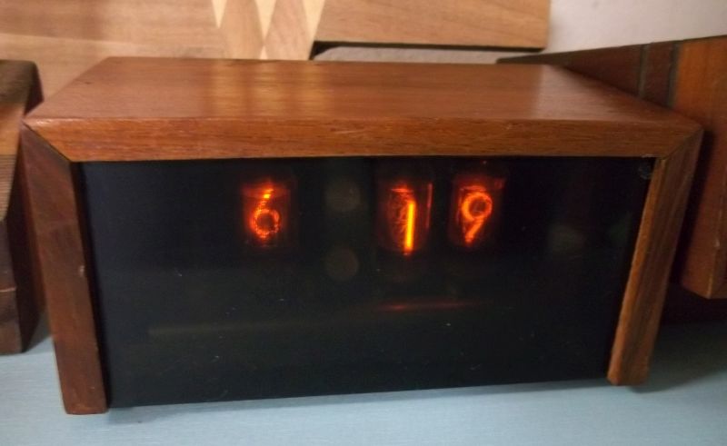
My Dad gets credit for the solid walnut case.

Image
The clock display unit has three Amperex ZM-1000 "Nixie" displays. The hours "1" is a long neon.

Image
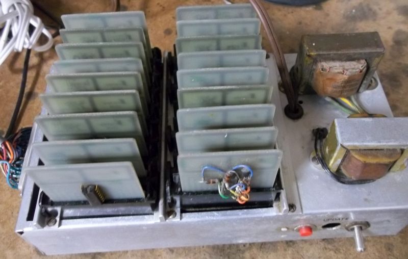
The clock base unit uses 19 RTL (resistor transistor logic) ICs mounted on individual plug-in cards.

Image
Most of the ICs are Motorola MC700-series RTL. A CMOS IC was installed "dead-bug" sometime in the 1980s due to failure.

Once I got a couple of Heathkit clocks I retired this unit.
It sat under my father's workbench for years absorbing sawdust, oil and dryer lint.

Sometime in the late 1980s or early 1990's I began phase one of the restoration replacing the 2N3055 regulator with a LM317.
An RTL IC failed and I had to cobble a dead-bug CMOS chip.
I later gave up because I realized it had become an unreliable pig.
The edgecards had became flakey and I didn't want to clean them and the receptacles.
The clock set in the garage and was later moved to the basement.
I decided, almost 50 years later to rescue it.

It took a can of Blue shower, a can of duster and a re-cap to bring it back to life.
Glad I did though.
March, 2021.

I really like this old clock and decided to complete the restoration by replacing the "dead bug" CMOS IC I used to replace a MC780P.

The MC780P is an RTL decade counter and was unavailable, or at least I thought so, back in the 1980s when I first restored the clock.
Thanks to the miracle of eBay I was able to recently buy some MC780s with a 1970 date code and used this now 51-year-old IC to repair my clock.

This IC hasn't been powered since it was tested the last week of May 1970.

Image

This is the third IC in that unit I've had to replace in the last 50 years so I decided to buy a few spares of the other RTL devices used.
Thanks to my newly-found MC780 I was able to replace the awful-looking dead bug.
Perhaps this clock will outlive me.

I took an inventory of the cards and it took 18 J-K flip flops (9 duals), 2 decade counters, 24 inverters, a dual 4 input NOR and three decoder-drivers.
19 ICs total.

I wished I could find the schematic for it - not so much to sort it out - but just to enjoy the trip back in time.

While going through a file folder I found this unique vintage clock from 1972 which predates the Mostek and National chips that made it easy.
It only uses 6 ICs and has a crystal timebase. https://proaudiodesignforum.com/images/ ... 3_1972.pdf

A couple of tricks make it unique and simple.
One is the offset in the hours display to simplify rollover from 12:00 to 1:00 and the other is using the decoded output to set counter modulus for the tens of minutes.

Image

The 1971-era metal gate 4000-series CMOS was IIRC pretty expensive at the time so I probably couldn't have afforded to make it.

This is a trip down memory lane: Now we'd do all of this with a PIC or Arduino.
User avatar
terkio
Posts: 304
Joined: Thu Feb 07, 2019 3:17 am
Contact:

Re: Vintage Digital Clock Circuits

Post by terkio »

Beautiful clok all designed and made of your own using RTL logic.
User avatar
terkio
Posts: 304
Joined: Thu Feb 07, 2019 3:17 am
Contact:

Re: Vintage Digital Clock Circuits

Post by terkio »

Beautiful clok all designed and made of your own using RTL logic.

This reminds me my first digital design with DTL logic to make a test equipment for a X Y plotter that basically had two ten bits counter. That was using boards of discrete components. Such boards were.
2 JK flip flop
6 Nand
I was already using synchronous logic. The two counters were of that kind. Decoding was done with two diode matrix boards with plenty of 1N914.
This equipment used two racks full of boards, backplane wiring was wire wrapping.
This equipment was for the French navy 1963 to plot lines at various X/Y ratios to check on linearity of the plotter. The plotter was to show the ship's location as well as four radar targets. All that stuff was electro mechanical with servos weighting about a quarter ton.
That was a student a summer job where I also had the opportunity to debug some of the plotter, onboard the ship.
User avatar
mediatechnology
Posts: 5437
Joined: Sat Aug 11, 2007 2:34 pm
Location: Oak Cliff, Texas
Contact:

Re: Vintage Digital Clock Circuits

Post by mediatechnology »

Thank you terkio.
That plotter tester sounds like fun.

The backplane on that clock, under the AMP edgecard connectors, was large gauge wire-wrap.
After a few years in use the clock began to get intermittent.
Some of it was the tin-plated edgecard connectors but what I found out later was that it was the Vcc and Ground buses becoming intermittent.
The buses were rigid metal strips that linked the boards and were the only soldered connections.
Over time those connections mechanically cracked.
I couldn't resolder them because of all the wire wrap connections so I had to bus them with bus wire and solder them out at the end of the pin.
I don't have the tooling for it anymore or I would have wire-wrapped it.

The whole base unit is a mess - I used whatever parts I could find in the garage and used whatever surplus my brother had.
I think the two MC780s were the only ICs and the 3X ZM-1000 displays I had to go to a distributor to buy.
I was 12 or 13 and using allowance money and whatever my brother paid me to help him with his surplus electronics business.

I should probably do a Nixie clock based on a Arduion Nano, DS-series RTC board and WiFi for NTP setting.
But its fun running this one with IC date codes dating back to 1967.
User avatar
mediatechnology
Posts: 5437
Joined: Sat Aug 11, 2007 2:34 pm
Location: Oak Cliff, Texas
Contact:

Re: Vintage Digital Clock Circuits

Post by mediatechnology »

I mentioned that I was buying a few spares for my 1972-era Nixie clock.
I scored a ZM1000 Nixie tube and when testing it I realized how beautiful it was.
I may buy a few more - I want to make a "modern" vintage clock.

To extend tube life and prevent ghosting my inner voice says not to multiplex them.
I haven't made up my mind if I'm going to use a PIC or something simple like the CMOS version posted earlier with the 4017 counters.
If I use a PIC that''s fine but by the time I demux for direct static drive I've used just as many ICs as a simple CMOS version.

ICs to drive Nixie tubes these days are pretty much limited to the Soviet 74141 equivalent, the K155ID1, or discrete transistors the MPSA42 being the most common.

My inner voice is telling me not to use the K155ID1 and I'm not sure why - they're widely available on eBay and not very expensive.
Part of it may be that they're a 4:10 decoder which precludes using a 4017 counter string which is already decoded.

What's surprising is that the 300V NPN MPSA42, which once used to be very plentiful and inexpensive, is now becoming obsolete.
A lot of manufacturers no longer make it.
Mouser carry ON Semi and Cherry Semiconductor.
The ON parts are on back order until November so there's still demand.
Once a part goes to Cherry - and they do a great job - you know its no longer considered mainstream by the manufacturers.
I have lots of the MPSA42 - we used them and the MPSA92 PNPs in the SSL Plasma meters.
For whatever reason the PNP would often fail with collector-base leakage.
I've read elsewhere that the MPSA42 can also be a little unreliable driving Nixies.

I began to look at using enhancement mode N-Ch MOSFETs and have found they work very well.
I tested my assumption using a BS170 and in the process found this old circuit using depletion mode FETs in the NSC FET Application note.

Image

With enhancement mode MOSFETs the source can be tied to ground.
The pre-bias line can be a simple Zener clamp to ground - the current level is uA.

The BS170, which is a 60V part can be made to work as well as the BS107 which is 240V.
The BS170 is still very common and multi-sourced; the BS107 is made by Zetex.
The BSS131 is also good but SMT.
IDSS is a critical spec and needs to be <<1 uA.
IDSS rules out a lot of HV N-Ch MOSFETs.

One of the disadvantages of using MPSA42s are the need for base resistors - the N-MOSFETs don't need it and can be driven directly by logic.
The disadvantage of the BS170 is that it's drain needs to be clamped at about 55V - the BS107 doesn't.
The 74141 also clamped it's open collector outputs at 55V in order to use a lower voltage process.

Regardless of whether or not I use a PIC, Arduino or simple CMOS I need a good reliable HV driver.
Whatever I wind up with I want to use commonly sourced parts everywhere I can - the only vintage part being the tubes.

I'll post some measurements of the ZM1000 and schematics of MOSFET drivers soon.
FrankLacy
Posts: 10
Joined: Tue Mar 16, 2021 5:35 pm

Re: Vintage Digital Clock Circuits

Post by FrankLacy »

Found this while cleaning. My first failed DIY project. I had no idea what I was doing.
ct7001.jpg
User avatar
mediatechnology
Posts: 5437
Joined: Sat Aug 11, 2007 2:34 pm
Location: Oak Cliff, Texas
Contact:

Re: Vintage Digital Clock Circuits

Post by mediatechnology »

Thanks for joining us Frank!

So does the IC work?
I have a CT7001 in a never-finished Radio Shack clock board.
I suppose it is a failed project too.
FrankLacy
Posts: 10
Joined: Tue Mar 16, 2021 5:35 pm

Re: Vintage Digital Clock Circuits

Post by FrankLacy »

I probably killed that poor IC in a dozen different ways.
User avatar
mediatechnology
Posts: 5437
Joined: Sat Aug 11, 2007 2:34 pm
Location: Oak Cliff, Texas
Contact:

Re: Vintage Digital Clock Circuits

Post by mediatechnology »

So Frank have you attempted any clocks since?

I just amassed 10 Amperex ZM1000 tubes so I think I need to build a 6 digit clock.
I got some BS107 drivers in and parts to build a HV boost converter for the 170V supply.
FrankLacy
Posts: 10
Joined: Tue Mar 16, 2021 5:35 pm

Re: Vintage Digital Clock Circuits

Post by FrankLacy »

No, that was the end of clocks for me. I moved on to modular synths. Analog synths are much more forgiving - if you build something correctly, it makes some weird noise; if you make some mistakes, it makes some other weird noise. I think my next digital project was a cosmac elf.
Post Reply