sr1200: Thanks for the post.
First let's look at the
physical polarity reversal on the encoder input and decoder output connectors:
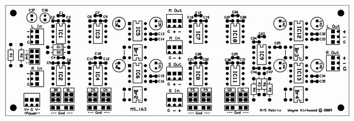
You'll notice on the encoder L and R input side "-" is on the top of the Phoenix connector and on the decoder L and R output "+" is on top. Check that first, because it could cause an overall polarity inversion in one or more of the paths.
Note also the
physical polarity inversion between the "M Out" and "M In" connectors. Dittos also for the S Out and S In. For test, just use a twisted pair and let them naturally cross-over.
Are you using the 5532 (or whatever OPA) -6dB stage? It inverts. (Which is why the PCB physical orientation is different on the L and R inputs/outputs.) If there's no 5532 in the path, and you're jumping around it, that could be another source of inversion. (The Mid and Side I/O has a physical inversion because it simplified layout.)
Check also the 1246 and 1240 stuffing. From left to right it's: 1246, 1240, 1646, 1246, 1240, 5532, 1646. If the 1246 and 1240's are swapped, things are going to be very weird sounding indeed.

EDIT. Been awhile since I had to think about this.

After visiting the "thinking chair" it came back to me:
A quick check of the encoder can be done by feeding L, R or both.
1) Feeding both L and R produces 2X Mid.
2) Feeding L only produces Mid and Side.
3) Feeding R only produces Mid and -Side.
Once the encoder is verified, loop M Out to M In, and S Out to S In.
Then, L In routes to L Out and R In routes to R Out with overall unity gain.
Look also at the jumpers for points B, C, F and G:
 External Polarity Inversion
Is a device connected into an insert (Mid or Side) that inverts polarity? Worth asking 'cause you never know...
The Mid Side Encoder and Decoder are the Same Thing. They are interchangeable in their roles.
One more thing I'll remind anyone using these is that the encoder and decoder matrices are the same thing. The only difference is the -6dB stage in the decoder.
Some people fret about the naturally-occurring +6 dB buildup in the encoder. Using the decoder as an encoder and the decoder as an encoder allows the Mid build-up to be reduced by the OPA stage.
We put the -6dB stage in the
decoder for a couple of reasons:
(1) The gain error that occurs from the 5532's external 1% resistors only affect L/R channel balance. If the decoder is used as an encoder, the tolerance of the discrete resistors reduce crosstalk performance.
(2) I'd rather use +/- 18V rails to pickup some headroom rather than reduce the natural Mid build-up or alter the ratio of Mid to Side. I suppose it's a matter of philosophy.
But you can have it both ways.
Let us know what you found.

