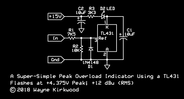
Re: A Super-Simple LED Peak Flasher Audio Overload Clipping Indicator Using the TL431
Posted: Tue May 01, 2018 5:27 pm
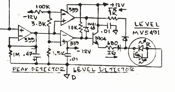
For the polar opposite of "simple" peak flasher, here is the overload indicator I designed back in 1991 for the big dog AMR consoles. Probably some 60 of them inside a single large format console.
While this looks like a lot, every part shown cost pennies (if that) and was machine inserted. The bicolor LED was the only hand inserted part.
The single most expensive part was the bicolor LED, green for signal present and red for overload (roughly 3dB before clipping). Next the dual op amp was maybe $0.12 to $0.13 (for two op amps so $0.07 ea).
The reason for all the complexity was for useful features. The input node labelled "smple" accepts the cathode end of multiple diodes sampling audio from several different points in the channel strip. This way we get both polarities of sine waves and sample signal levels pre/post fader/EQ.
The green "signal present" starts lighting around -20dBu with somewhat modulated brightness, but the LED current for both polarities is steered or stolen from the resistor divider string spanning between the two rails so zero net ground current, and PS current draw is incremental or modulated, while the LED itself exhibits some snap action for sharper knee behavior.
The signal present is incremental and modulated while the overload indication has positive feedback hysteresis so even narrow spikes will indicate long enough to be seen by users (while I didn't test it at 500 kHz, my console didn't pass 500kHz).
As typical for my old designs, lots of moving parts and a bunch going on that may not be immediately obvious.
JR

