A rundown on some tests and personal discoveries about LC filters, and viewed in the context of a Pultec MEQ filter clone. In my build, we see 11.2 dB cuts and 9 dB boosts.
Some of the plots here were done with 5Hz resolution, so the bottom is bumpy and imperfect.
I added some additional low bands after experimentation, which come out more like shelves. 45 Hz and 112 Hz on bottom, shown at full, half pot travel, and 1 dB boost.
Upper bands show additional 7K and 10K boost positions. After hearing (dog whistles) and seeing the bandwidth of 7-10K, I ditched them in favor of 700 and 1K in the upper boost section, due to wider shapes. Added 1K looks about the same as the existing, the extra 700 is much wider.
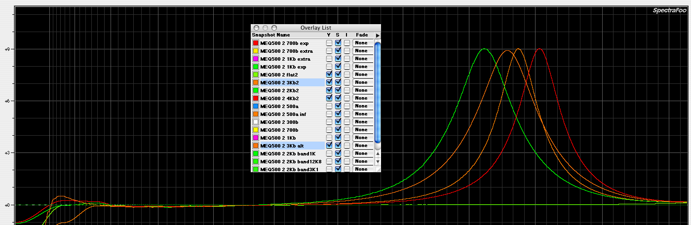
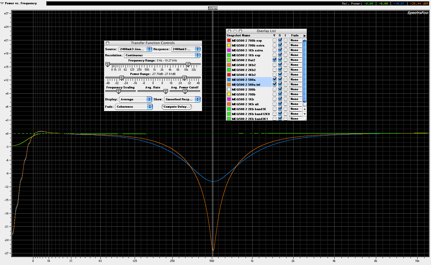
Varying reverse engineering and modifications show the 3K boost position on differing inductance taps. I checked both and found these bandwidth differences, 3K being the orange options. I prefer the wider shape match of the 477mH tap over the 625mH.
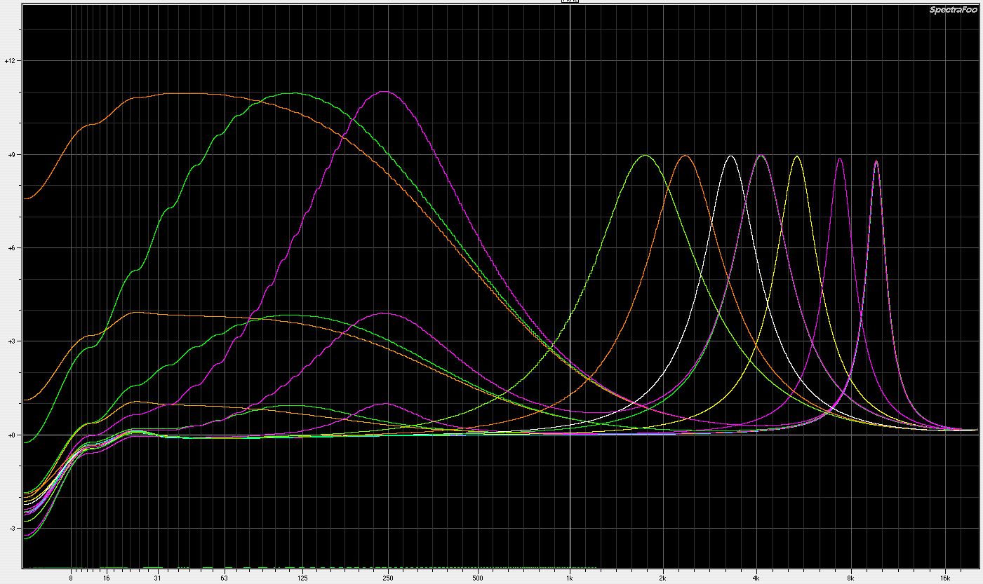
A potentially confusing compilation of all these boost options, with 300 thrown in for bandwidth comparison. It should be observed that Pultec decided to go with very narrow high boosts in the MEQ, as opposed to the broad boost shapes of the EQP program EQ.
----------
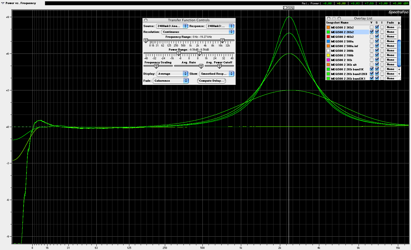
It was suggested that bandwidth switches might be added to all three bands, since the cut band already has a depth limit R. IMO, bandwidth switches are useless. They hardly change the shape at all. For boosts, they simply restrict the boost amount. At the shallowest settings you get a bit more overall width (significant maybe with max +3 or less!), but hardly enough to be worth the extra switching. Stock, 1K, 3K1, 12K8 series resistance values shown, corresponding to +9, +7.7, +6, +3 max boost ranges. As you can also guess, changing the bandwidth will bump your total boost, so it's not even simple to compare apples to apples.
Shorting 270R in the attenuation band simply extends the depth of the existing shape.
-----------------
Some experiments with altering the shunt values in the filter section, the 1K and the 5.1K.
changing 1K shunt to 363 ohms increases overall loss another -6dB, 3.75 dB sharper boost at 300, 0.25 dB sharper at 4K.
changing 1K shunt to 13 ohms increases overall loss another -32dB, 11 dB sharper boost at 300, 0.5 dB sharper at 4K.
changing 5.1K shunt to 2025 ohms increases overall loss another -6dB, no sharper boost at 300, 4.5 dB sharper at 4K.
changing 5.1K shunt to 69 ohms increases overall loss another -33.5dB, no sharper boost at 300, 12.75 dB sharper at 4K.
for 1K cut, almost identical comparison between 1K and 5.1K changes; 3.25 dB deeper and slightly wider shape at max change.
Existing max deviation selections appear best compromise for action versus noise. These plots are leveled for identical flat response, you should be able to figure out which curve is which. For each freq, standard/1st opt/2nd opt. Blue plots are the individual stock 300 and 4K for comparison.
-----------------
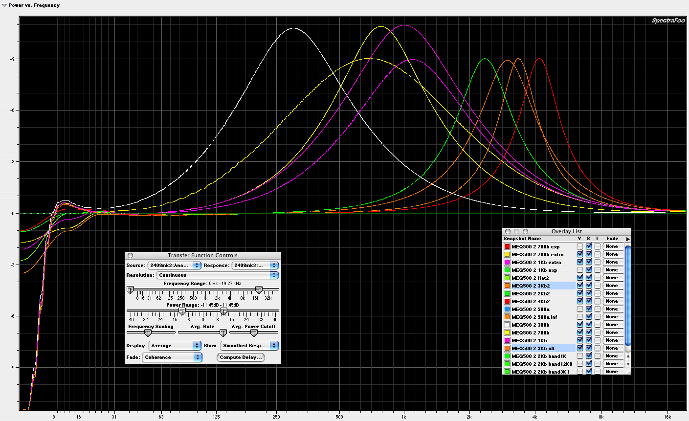
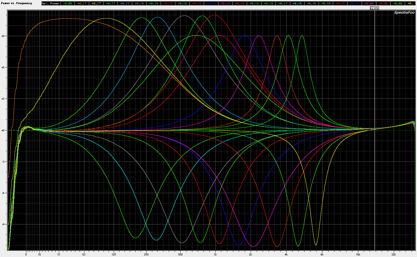
Here are the compiled curves as it progressed. 4K cut is missing, and the 3K boost is still the narrower option. A fair number of frequencies are still significantly off from the official points, and remain to be trimmed in. Luckily in my build, the frequencies are all higher than specified, so additional parallel capacitance will trim them into position.
I am happy with the frequency additions so far. The 40 and 100 boosts are broad and useful, and the extra 700 and 1K in the high boost band are good in combination with the 40 and 100, especially on bass.
I looked at a variety of other shape bending methods, which will have to be another post, another day. Suffice to say I mostly grasp where Manley went with their Massive Passive.
LC filter experiments, in Pultec MEQ context
LC filter experiments, in Pultec MEQ context
Best,
Doug Williams
Electromagnetic Radiation Recorders
Doug Williams
Electromagnetic Radiation Recorders
-
mediatechnology

- Posts: 5456
- Joined: Sat Aug 11, 2007 2:34 pm
- Location: Oak Cliff, Texas
- Contact:
Re: LC filter experiments, in Pultec MEQ context
Doug: FWIW I look at this and see an AES paper in progress. Great work.
Re: LC filter experiments, in Pultec MEQ context
Thanks. I haven't seen anything this explicit, always more broad theory without specific examples.
There must be a paper already, probably an IRE paper before AES existed.
There must be a paper already, probably an IRE paper before AES existed.
Best,
Doug Williams
Electromagnetic Radiation Recorders
Doug Williams
Electromagnetic Radiation Recorders
-
mediatechnology
- Posts: 5456
- Joined: Sat Aug 11, 2007 2:34 pm
- Location: Oak Cliff, Texas
- Contact:
Re: LC filter experiments, in Pultec MEQ context
You've got me curious about any non-audio work Pulse Techniques did. Wonder if they did military contracting...
Re: LC filter experiments, in Pultec MEQ context
I've never heard of any non-audio work. My understanding is the shop was pretty small.
I have had a few Gov notch filters from the same era, and the build quality is far beyond what I've ever seen in a Pultec product. I don't think they were ever thinking about the requirements of that market.
I have had a few Gov notch filters from the same era, and the build quality is far beyond what I've ever seen in a Pultec product. I don't think they were ever thinking about the requirements of that market.
Best,
Doug Williams
Electromagnetic Radiation Recorders
Doug Williams
Electromagnetic Radiation Recorders
-
mediatechnology
- Posts: 5456
- Joined: Sat Aug 11, 2007 2:34 pm
- Location: Oak Cliff, Texas
- Contact:
Re: LC filter experiments, in Pultec MEQ context
Doug - I did a patent search for Eugene Shenk and it appears that a large body of his work was in telegraph systems and pulse reconstruction/synchronization. Most of his work looks to be assigned to RCA. I never could figure out how an audio company in that era could wind up with a name of Pulse Techniques. Today yes, cir. 1950 no. I think program equalizers may have been a side gig (or retirement gig) to telegraphy and "pulses" were his thing.
Here's one of his telegraphy patents: http://www.google.com/patents?id=yJdCAA ... ages&cad=1#
Same Eugene R. Shenk? Would like to learn more about his patents.
Here's one of his telegraphy patents: http://www.google.com/patents?id=yJdCAA ... ages&cad=1#
Same Eugene R. Shenk? Would like to learn more about his patents.
Re: LC filter experiments, in Pultec MEQ context
That's interesting stuff. I have never seen any mention of this work, or of any association with RCA. I would assume it's him. The earliest references I've found have had to do with running a studio, modifying various surplus Altec amps, and making some of the earliest Pultec branded custom recording equipment. I spoke with him once via email, maybe 5-6 years ago, and he mentioned having been an audio dealer for Altec equipment, so I've always thought of him as exclusively audio. Another possible historical aspect to keep an eye on.
Best,
Doug Williams
Electromagnetic Radiation Recorders
Doug Williams
Electromagnetic Radiation Recorders
-
mediatechnology
- Posts: 5456
- Joined: Sat Aug 11, 2007 2:34 pm
- Location: Oak Cliff, Texas
- Contact:
Re: LC filter experiments, in Pultec MEQ context
One of Eugene's patents at RCA deals with an AM modulator. He may have spent some time in their broadcast division.

I'd like to see someone try the MEQ/PEQ network driven differentially by a THAT1646 (or dual current-boosted pair of 1646) with a 1246 diff amp receiving the output before 1646 rebalancing. It might be quieter and less sensitive to fields. There would be a 6 dB headroom boost too.
I'd like to see someone try the MEQ/PEQ network driven differentially by a THAT1646 (or dual current-boosted pair of 1646) with a 1246 diff amp receiving the output before 1646 rebalancing. It might be quieter and less sensitive to fields. There would be a 6 dB headroom boost too.
Re: LC filter experiments, in Pultec MEQ context
I did use the 1246 and 1646 current boost as input stage. You need about 24 dB make up gain on the output side to get back to unity. Certainly no reason an appropriate IC gain stage driving a 1646 couldn't do the job.
Best,
Doug Williams
Electromagnetic Radiation Recorders
Doug Williams
Electromagnetic Radiation Recorders
-
mediatechnology
- Posts: 5456
- Joined: Sat Aug 11, 2007 2:34 pm
- Location: Oak Cliff, Texas
- Contact:
Re: LC filter experiments, in Pultec MEQ context
What I was suggesting is a little different. What I'm proposing here is a hybrid Pultec with solid-state electronics that is (almost) fully balanced end-to-end.
1) Lift the ground line at the input transformer and remove the transformer. Receive the input with a 1246 as you've done already.
2) Here's where it changes: Drive the filter network differentially in "push-pull" with a 1646 or 1646 x2. I see that a single "SE" drive 1646 worked well here from your other post. Using balanced drive, both legs of the network are now driven, it's floating, and the magnetics can be driven twice as hard. Headroom/dynamic range in the filter network increases by 6 dB.
3) Receive the filter network output as "push-pull" into a differential amp. Not really push-pull, but balanced differential drive with both legs of the network driven. Common mode hum fields, either magnetic or electrostatic, entering the MEQ network should be attenuated.
4) Sounds like the diff amp on the output would need 24 dB of make-up gain. Since the MEQ network output "sees" (I'm assuming) a relatively low impedance load from the interstage transformer a mic preamp suited for source impedances <<2K might make a quieter stage than a 553X or whatever op amp one would want to use. Use a THAT1512 to provide the 24 dB make-up gain. This gives you low voltage noise and the 1512's output diff amp provides CM rejection.
5) The 1512 output drives a final 1646.
BTW you can take two 1646's and parallel them to boost the current drive but still have balanced output. I don't recall if I did that with OutSmarts on. I think I did. What you do is parallel pins 4 (diff input) pins 1, and pins 8. This way you get twice the current and twice the P-P swing. Since the 1646 have 25R output resistors no ballasting is required. You can literally solder a 1646 on top of another 1646 to boost the output drive current.
I'm at my other house - and am scannerless - or I'd draw something.